Nissan Frontier. Manual - part 334


  Index      Nissan     Nissan Frontier (2014 year) - Service and Repair Manual


Search            


Content   ..  332  333  334  335   ..


Nissan Frontier. Manual - part 334


DLN-238

< UNIT DISASSEMBLY AND ASSEMBLY >

[C200]

REAR FINAL DRIVE

13. Remove the Tool from the gear carrier and disassemble to

retrieve the drive pinion bearings.
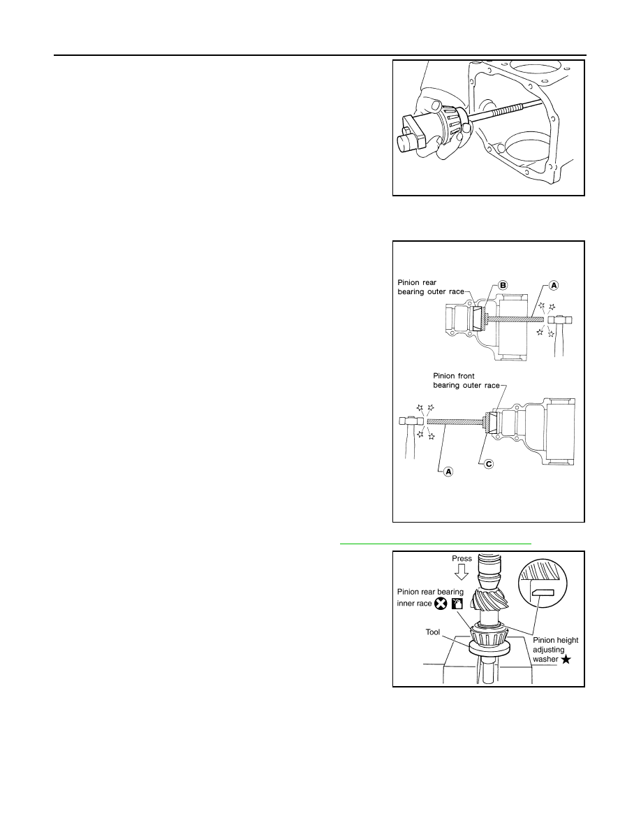
ASSEMBLY

Drive Pinion Assembly

1. Install the new drive pinion front and rear bearing outer races

using Tools.

CAUTION:

• First tap the drive pinion bearing outer race until it

becomes flush with the gear carrier.

• Do not reuse drive pinion front and rear bearing outer

race.

2. Select a drive pinion height adjusting washer. Refer to 

DLN-225, "Disassembly and Assembly"

.

3. Install the selected drive pinion height adjusting washer to the

drive pinion. Press the new drive pinion rear bearing inner race

to it using Tool.

CAUTION:

• Install the drive pinion height adjusting washer in the

proper direction as shown.

• Do not reuse drive pinion rear bearing inner race.

Tool number

 (J-34309)

SPD205A

Tool number

(A): ST30611000 (J-25742-1)
(B): ST30621000 (J-25742-5)
(C): ST30613000 (J-25742-3)

SPD679

Tool number

: ST30901000 (J-26010-01)

SDIA0048E

REAR FINAL DRIVE

DLN-239

< UNIT DISASSEMBLY AND ASSEMBLY >

[C200]

C

E

F

G

H

I

J

K

L

M

A

B

DLN

N

O

P

4. Assemble the new collapsible spacer to the drive pinion.

CAUTION:

Do not reuse collapsible spacer.

5. Apply differential gear oil to the drive pinion rear bearing, and

install the drive pinion assembly to the gear carrier.

6. Apply differential gear oil to the drive pinion front bearing, and

install the new drive pinion front bearing inner race to the drive

pinion assembly.

CAUTION:

Do not reuse drive pinion front bearing inner race.

7. Press the drive pinion front bearing inner race to the drive pinion

as far as drive pinion lock nut can be tightened using suitable

spacer.

8. Apply multi-purpose grease to the lips and differential gear oil to

the circumference of the new front oil seal. Then drive the new

front oil seal in evenly until it becomes flush with the gear carrier

using Tool.

CAUTION:

• Do not reuse front oil seal.

• Do not incline the new front oil seal when installing.

• Apply multi-purpose grease to the lips and differential

gear oil to the circumference of the new front oil seal.

9. Install the companion flange to the drive pinion while aligning the matching marks.

SPD222

SPD896

Tool number

: KV38100500 (J-25273)

PDIA0563E

DLN-240

< UNIT DISASSEMBLY AND ASSEMBLY >

[C200]

REAR FINAL DRIVE

10. Apply anti-corrosive oil to the threads of the drive pinion and the

seating surface of the new drive pinion lock nut. Then adjust the

drive pinion lock nut tightening torque using suitable tool (A),

and check the drive pinion bearing preload torque using Tool

(B).

CAUTION:

• Do not reuse drive pinion lock nut.

• Apply anti-corrosive oil to the threads of the drive pinion

and the seating surface of the new drive pinion lock nut.

• Adjust the drive pinion lock nut tightening torque to the

lower limit first. Do not exceed the drive pinion lock nut

specified torque. Refer to 

DLN-225, "Disassembly and

Assembly"

.

• If the drive pinion bearing preload torque exceeds the

specified value, replace collapsible spacer and tighten it

again to adjust. Do not loosen drive pinion lock nut to

adjust the drive pinion bearing preload torque.

• After adjustment, rotate drive pinion back and forth 2 to 3

times to check for unusual noise, rotation malfunction, and other malfunctions.

11. Check companion flange runout. Refer to 

DLN-225, "Disassembly and Assembly"

.

12. Install differential case assembly. Refer to 

DLN-225, "Disassembly and Assembly"

.

Differential Assembly

1. Install side gear thrust washers with the same thickness as the

ones installed prior to disassembly, or reinstall the old ones on

the side gears.

2. Install the side gears and side gear thrust washers into the dif-

ferential case.

CAUTION:

Make sure that the circular clip is installed to side gears.

3. Install the pinion mate thrust washers to the two pinion mate

gears. Then install the pinion mate gears with the pinion mate

thrust washers by aligning them in diagonally opposite positions

and rotating them into the differential case.

Tool number

(B): ST3127S000 (J-25765-A)

Drive pinion bearing preload torque:

Refer to 

DLN-244, "Inspection and Adjustment"

WDIA0379E

SDIA0193J

SDIA2025E

REAR FINAL DRIVE

DLN-241

< UNIT DISASSEMBLY AND ASSEMBLY >

[C200]

C

E

F

G

H

I

J

K

L

M

A

B

DLN

N

O

P

4. Align the lock pin hole on the differential case with the lock pin

hole on the pinion mate shaft, and install the pinion mate shaft.

5. Measure the side gear end play. If necessary, select the appro-

priate side gear thrust washers. Refer to 

DLN-225, "Disassem-

bly and Assembly"

.

6. Drive a new lock pin into the pinion mate shaft until it is flush

with the differential case using suitable tool.

CAUTION:

Do not reuse lock pin.

7. Align the matching mark of the differential case with the mark of

the drive gear, then place the drive gear onto the differential

case.

8. Apply thread locking sealant into the threaded holes of the drive

gear and install the bolts.

• Use Genuine Medium Strength Thread Locking Sealant or

equivalent. Refer to 

GI-21, "Recommended Chemical Prod-

ucts and Sealants"

.

CAUTION:

Make sure the drive gear back and threaded holes are

clean.

9. Tighten the drive gear bolts to the specified torque. Refer to

DLN-225, "Disassembly and Assembly"

. After tightening the

drive gear bolts to the specified torque, tighten an additional 31

°

to 36

° using Tool (A).

CAUTION:

• Always use Tool. Avoid tightening based on visual check

alone.

• Tighten drive gear bolts in a crisscross pattern.

SDIA0195J

SPD030

SDIA2593E

SDIA2594E

Tool number

: KV10112100-A (BT-8653-A)

AWBIA0722ZZ


Content   ..  332  333  334  335   ..