Nissan Frontier. Manual - part 325


  Index      Nissan     Nissan Frontier (2014 year) - Service and Repair Manual


Search            


Content   ..  323  324  325  326   ..


Nissan Frontier. Manual - part 325


DLN-202

< UNIT DISASSEMBLY AND ASSEMBLY >

[FRONT FINAL DRIVE: R180A]

FRONT FINAL DRIVE

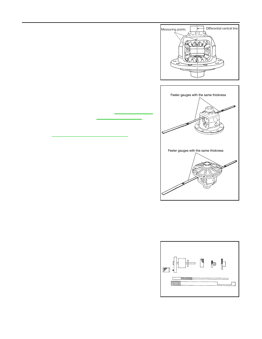
1. Place the differential case straight up so that the side gear to be

measured is upward.

2. Using feeler gauges, measure the clearance between the side

gear back and differential case at three different points, while

rotating the side gear. Average the three readings to calculate

the clearance. (Measure the clearance of the other side as well.)

• If the side gear back clearance is outside of the specification,

use a thicker or thinner side gear thrust washer to adjust.

Refer to 

DLN-212, "Inspection and Adjustment"

.

CAUTION:

• Insert feeler gauges with the same thickness on both

sides to prevent side gear from tilting.

• Each gear should rotate smoothly without excessive

resistance during differential motion.

• Select a side gear thrust washer for right and left individually.

NOTE:

Side gear back clearance is clearance between side gear and differential case for adjusting side gear

backlash.

Drive Pinion Height

1. Make sure all parts are clean and that the bearings are well lubricated.
2. Assemble the drive pinion bearings onto the Tool.

PDIA0460E

Side gear back clearance: Refer to 

DLN-212, "Inspec-

tion and Adjustment"

If the side gear back clearance is greater than 
specification:

Use a thicker side gear thrust washer.

If the side gear back clearance is less than spec-
ification:

Use a thinner side gear thrust washer.

PDIA0576E

Tool number

 (J-34309)

SPD769

FRONT FINAL DRIVE

DLN-203

< UNIT DISASSEMBLY AND ASSEMBLY >

[FRONT FINAL DRIVE: R180A]

C

E

F

G

H

I

J

K

L

M

A

B

DLN

N

O

P

• Drive pinion front bearing; make sure the J-34309-3 drive

pinion front bearing seat is secured tightly against the J-

34309-2 gauge anvil. Then turn the J-34309-7 drive pinion

front bearing pilot to secure the drive pinon front bearing in its

proper position.

• Drive pinion rear bearing; the J-34309-8 drive pinion rear

bearing pilot is used to center the drive pinion rear bearing

only. The J-34309-4 drive pinion rear bearing locking seat is

used to lock the drive pinion rear bearing to the assembly.

• Installation of J-34309-9 and J-34309-16; place a suitable

2.5 mm (0.098 in) thick plain washer between J-34309-9 and

J-34309-16. Both surfaces of J-34309-9 and J-34309-16 must

be parallel with a clearance of 2.5 mm (0.098 in).

3. Install the drive pinion rear bearing inner race into the gear car-

rier. Then insert the drive pinion height adjusting washer selec-

tor tool, J-34309-1, gauge screw assembly.

4. Assemble the drive pinion front bearing inner race and the J-

34309-2 gauge anvil. Assemble them together with the J-34309-

1 gauge screw in the gear carrier. Make sure that the drive pin-

ion height gauge plate, J-34309-16, will turn a full 360

°. Tighten

the two sections together by hand.

5. Turn the assembly several times to seat the drive pinon bear-

ings.

SPD197A

SPD893

SPD199A

SPD770

DLN-204

< UNIT DISASSEMBLY AND ASSEMBLY >

[FRONT FINAL DRIVE: R180A]

FRONT FINAL DRIVE

6. Measure the turning torque at the end of the J-34309-2 gauge

anvil using Tool.

7. Place the J-34309-10 “R180A” drive pinion height adapter onto

the gauge plate and tighten it by hand.

CAUTION:

Make sure all machined surfaces are clean.

8. Position the side bearing discs, Tool, and arbor firmly into the

side bearing bores. Install the side bearing caps and tighten the

side bearing cap bolts to the specified torque. Refer to 

DLN-193,

"Disassembly and Assembly"

.

9. Select the correct standard drive pinion height adjusting washer

thickness. Select by using a standard gauge of 3 mm (0.12 in)

and your J-34309-101 feeler gauge. Measure the distance

between the J-34309-10 drive pinion height adapter, including

the standard gauge and the arbor.

10. Write down the exact measurement (the value of feeler gauge).

Tool number

: ST3127S000 (J-25765- A)

Turning torque specification:

1.0 - 1.6 N·m (0.11 - 0.16 kg-m, 9 - 14 in-lb)

PDIA0566E

SPD208A

Tool number

 (J-25269-18)

SPD211A

SPD204A

SPD775

FRONT FINAL DRIVE

DLN-205

< UNIT DISASSEMBLY AND ASSEMBLY >

[FRONT FINAL DRIVE: R180A]

C

E

F

G

H

I

J

K

L

M

A

B

DLN

N

O

P

11. Correct the drive pinion height adjusting washer size by referring

to the drive pinion “head number”.

There are two numbers painted on the drive pinion. The first

one refers to the drive pinion and drive gear as a matched

set. This number should be the same as the number on the

drive gear. The second number is the drive pinion “head

number”. It refers to the ideal drive pinion height from stan-

dard for quietest operation. Use the following chart to

determine the correct drive pinion height adjusting washer.

12. Select the correct drive pinion height adjusting washer. Refer to 

DLN-212, "Inspection and Adjustment"

.

13. Remove the Tool from the gear carrier and disassemble to

retrieve the drive pinion bearings.

ASSEMBLY

Drive Pinion Assembly

Head number

Add or remove from the standard drive pinion 

height adjusting washer thickness measurement

- 6
- 5
- 4
- 3
- 2
- 1

0

+1
+2
+3
+4
+5 
+6

Add 0.06 mm (0.0024 in)
Add 0.05 mm (0.0020 in)
Add 0.04 mm (0.0016 in)
Add 0.03 mm (0.0012 in)
Add 0.02 mm (0.0008 in)
Add 0.01 mm (0.0004 in)

Use the selected washer thickness

Subtract 0.01 mm (0.0004 in)
Subtract 0.02 mm (0.0008 in)
Subtract 0.03 mm (0.0012 in)
Subtract 0.04 mm (0.0016 in)
Subtract 0.05 mm (0.0020 in)
Subtract 0.06 mm (0.0024 in)

Tool number

 (J-34309)

SPD542

SPD205A


Content   ..  323  324  325  326   ..