Nissan Frontier. Manual - part 324


  Index      Nissan     Nissan Frontier (2014 year) - Service and Repair Manual


Search            


Content   ..  322  323  324  325   ..


Nissan Frontier. Manual - part 324


DLN-198

< UNIT DISASSEMBLY AND ASSEMBLY >

[FRONT FINAL DRIVE: R180A]

FRONT FINAL DRIVE

Differential Assembly

1. Remove differential side shaft assembly. Refer to 

DLN-189, "Removal and Installation"

.

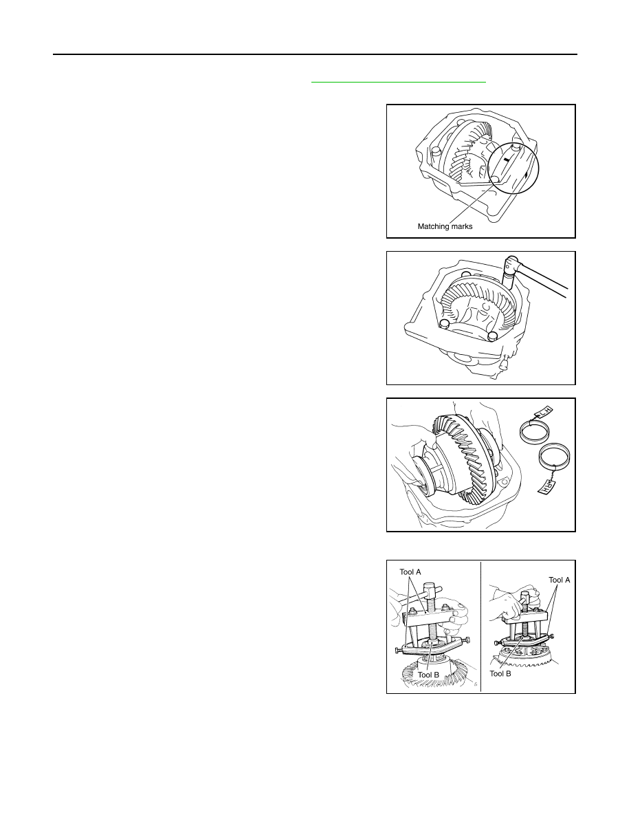
2. Remove side seal from gear carrier using suitable tool.
3. For proper reinstallation, paint matching marks on one side of

the side bearing cap and gear carrier.

CAUTION:

• For matching marks, use paint. Do not damage side bear-

ing cap or gear carrier.

• Side bearing caps are line-board during manufacture. The

matching marks are used to reinstall them in their original

positions.

4. Remove the side bearing caps.

5. Lift the differential case assembly out of the gear carrier.

CAUTION:

• Keep side bearing outer races together with side bearing

inner races. Do not mix them up.

• Keep side bearing adjusting washers together with side

bearings.

6. Remove housing spacer.
7. Remove side bearing inner race using Tools as shown.

CAUTION:

• Do not remove side bearing inner race unless it is being

replaced.

• Place copper plates between the vise and the side bearing

inner race and drive gear to prevent damage.

PDIA0700E

PDIA0701E

SPD919

Tool number

 (A): ST33051001 (J-22888-20)
 (B): ST33061000 (J-8107-2)

PDIA0827E

FRONT FINAL DRIVE

DLN-199

< UNIT DISASSEMBLY AND ASSEMBLY >

[FRONT FINAL DRIVE: R180A]

C

E

F

G

H

I

J

K

L

M

A

B

DLN

N

O

P

• Keep side bearing outer races together with side bearing

inner races. Do not mix them up.

8. For proper reinstallation, paint matching marks on the differential

case and drive gear.

CAUTION:

Use paint for matching marks. Do not damage differential

case or drive gear.

9. Remove the drive gear bolts.
10. Tap the drive gear off the differential case using suitable tool.

CAUTION:

Tap evenly all around to keep drive gear from bending.

11. Remove the lock pin of the pinion mate shaft from the drive gear

side using suitable tool.

12. Remove the pinion mate shaft.

13. Turn the pinion mate gear, then remove the pinion mate gear,

pinion mate thrust washer, side gear and side gear thrust

washer from the differential case.

SPD022

PDIA0496E

SPD025

SDIA0031J

SDIA0032J

DLN-200

< UNIT DISASSEMBLY AND ASSEMBLY >

[FRONT FINAL DRIVE: R180A]

FRONT FINAL DRIVE

Drive Pinion Assembly

1. Remove the differential assembly. Refer to 

DLN-193, "Disassembly and Assembly"

.

2. Remove the drive pinion lock nut using suitable tool.
3. Put matching marks on the companion flange and drive pinion

using paint.

CAUTION:

Use paint to make the matching marks. Do not damage the

companion flange or drive pinion.

4. Remove the companion flange using suitable tool.

5. Press the drive pinion assembly (with rear inner bearing race

and collapsible spacer) out of the gear carrier.

CAUTION:

Do not drop drive pinion assembly.

6. Remove the drive pinion rear bearing inner race and drive pinion

height adjusting washer using Tool.

PDIA0702E

PDIA0703E

PDIA0704E

Tool number

: ST30031000 (J-22912-01)

S-PD179

FRONT FINAL DRIVE

DLN-201

< UNIT DISASSEMBLY AND ASSEMBLY >

[FRONT FINAL DRIVE: R180A]

C

E

F

G

H

I

J

K

L

M

A

B

DLN

N

O

P

7. Remove the front oil seal using suitable tool.

CAUTION:

Do not damage gear carrier.

8. Remove the drive pinion front bearing inner race.
9. Remove the drive pinion front and rear bearing outer races by

tapping them uniformly using suitable tool.

CAUTION:

Do not damage gear carrier.

INSPECTION AFTER DISASSEMBLY

Clean the disassembled parts. Then inspect the parts for wear or damage. If wear or damage are found, follow

the measures below.

Drive Pinion and Drive Gear

• If the drive pinion and drive gear teeth do not mesh or line-up correctly, determine the cause and adjust,

repair, or replace as necessary.

• If the drive pinion or drive gear are worn, cracked, damaged, pitted or chipped (by friction) noticeably,

replace with new drive pinion and drive gear.

• Drive pinion and drive gear are supplied in matched sets only. Matching numbers on both drive pinion and

drive gear are etched for verification. If a new drive pinion and drive gear set are being used, verify the num-

bers of each drive pinion and drive gear before proceeding with assembly.

Bearing

• If bearings are chipped (by friction), pitted, worn, rusted, scratched, or unusual noise is coming from bearing,

replace with new bearing assembly (as a new set).

• Bearing must be replaced with a new one whenever disassembled.

Side Gear and Pinion Mate Gear

• If any cracks or damage are found on the surface of the teeth, replace with new one.

• If any worn or chipped marks are found on the side of the side gear and pinion mate gear which contact the

thrust washer, replace with new one.

• Replace both side gear and pinion mate gear as a set when replacing side gear or pinion mate gear.

Side Gear Thrust Washer and Pinion Mate Thrust Washer

• If any chips (by friction), damage, or unusual wear are found, replace with new one.

Gear Carrier

• If any wear or cracks are found on the contact sides of gear carrier, replace with new one.

Companion Flange

• If any chips (about 0.1mm, 0.004 in) or other damage on the companion flange surface which contacts the

front oil seal lips are found, replace with new one.

ADJUSTING AND SELECTING WASHERS

Side Gear Back Clearance

• Assemble the differential parts if they are disassembled. Refer to 

DLN-193, "Disassembly and Assembly"

.

PDIA0716E

PDIA0705E


Content   ..  322  323  324  325   ..