Nissan Frontier. Manual - part 248


  Index      Nissan     Nissan Frontier (2014 year) - Service and Repair Manual


Search            


Content   ..  246  247  248  249   ..


Nissan Frontier. Manual - part 248


DLK-38

< DTC/CIRCUIT DIAGNOSIS >

DOOR LOCK AND UNLOCK SWITCH

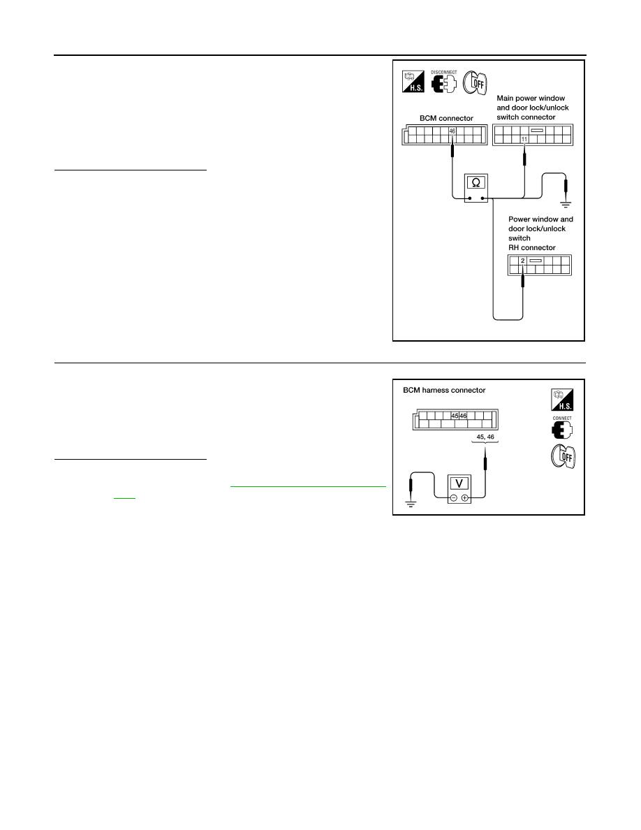
5. Check continuity between BCM connector M19 terminal 46 and

ground.

Is the inspection result normal?

YES

>> GO TO 5

NO

>> Repair or replace harness.

5.

CHECK BCM OUTPUT VOLTAGE

1. Connect BCM.

2. Check voltage between BCM connector M19 terminals 45, 46

and ground.

Is the inspection result normal?

YES

>> Check condition of the harness and connector.

NO

>> Replace BCM. Refer to 

BCS-49, "Removal and Installa-

tion"

.

2 - 46

: Continuity should exist.

11 - 46

: Continuity should exist.

46 - Ground

: Continuity should not exist.

WIIA0631E

45 - Ground

: Battery voltage

46 - Ground

: Battery voltage

LIIA1351E

KEY CYLINDER SWITCH

DLK-39

< DTC/CIRCUIT DIAGNOSIS >

C

D

E

F

G

H

I

J

L

M

A

B

DLK

N

O

P

KEY CYLINDER SWITCH

DRIVER SIDE
DRIVER SIDE : Description

INFOID:0000000009478894

The main power window and door lock/unlock switch detects condition of the door key cylinder switch and

transmits to BCM as the LOCK or UNLOCK signal. 

DRIVER SIDE : Component Function Check

INFOID:0000000009478895

1.

CHECK DOOR KEY CYLINDER SWITCH INPUT SIGNAL

Check "KEY CYL LK-SW" AND "KEY CYL UN-SW" in Data Monitor mode for “DOOR LOCK” with CONSULT.

Is the inspection result normal?

YES

>> Key cylinder switch is OK.

NO

>> Refer to 

DLK-39, "DRIVER SIDE : Diagnosis Procedure"

.

DRIVER SIDE : Diagnosis Procedure

INFOID:0000000009478896

Regarding Wiring Diagram information, refer to 

DLK-77, "Wiring Diagram - King Cab"

 or 

DLK-87, "Wiring Dia-

gram - Crew Cab"

.

1.

CHECK DOOR KEY CYLINDER SWITCH LH

With CONSULT

Check front door lock assembly LH (key cylinder switch) ("KEY CYL LK-SW") and ("KEY CYL UN-SW) in

DATA MONITOR mode in CONSULT. Refer to 

BCS-15, "DOOR LOCK : CONSULT Function (BCM - DOOR

LOCK)"

.

• When key inserted in front key cylinder is turned to LOCK:

• When key inserted in front key cylinder is turned to UNLOCK:

Without CONSULT

Check voltage between BCM connector M18 terminals 7, 8 and

ground.

Monitor item

Condition

KEY CYL LK-SW

Lock

: ON

Neutral / Unlock

: OFF

KEY CYL UN-SW

Unlock

: ON

Neutral / Lock

: OFF

KEY CYL LK-SW

: ON

KEY CYL UN-SW

: ON

Connector

Terminals

Condition

Voltage (V)

(Approx.)

(+)

(–)

M18

7

Ground

Neutral/Lock

1.5

Unlock

0

8

Neutral/Unlock

1.5

Lock

0

WIIA0457E

DLK-40

< DTC/CIRCUIT DIAGNOSIS >

KEY CYLINDER SWITCH

Is the inspection result normal?

YES

>> Front door lock assembly LH (key cylinder switch) signal is OK.

NO

>> GO TO 2

2.

CHECK FRONT DOOR LOCK ASSEMBLY LH (KEY CYLINDER SWITCH)

1. Turn ignition switch OFF.

2. Disconnect front door lock assembly LH (key cylinder switch).

3. Check continuity between front door lock assembly LH (key cyl-

inder switch) connector terminals 3, 4 and 5.

Is the inspection result normal?

YES

>> GO TO 3

NO

>> Replace front door lock assembly LH (key cylinder switch). Refer to 

DLK-137, "Removal and

Installation"

.

3.

CHECK FRONT DOOR LOCK ASSEMBLY LH HARNESS

1. Disconnect BCM.

2. Check continuity between BCM connector M18 terminals 7, 8

and front door lock assembly LH connector D14 terminals 3, 5.

3. Check continuity between BCM connector M18 terminals 7, 8

and ground.

Is the inspection result normal?

YES

>> GO TO 4

NO

>> Repair or replace harness.

4.

CHECK FRONT DOOR LOCK ASSEMBLY LH GROUND

Check continuity between front door lock assembly LH connector

D14 terminal 4 and ground.

Is the inspection result normal?

YES

>> GO TO 5

NO

>> Repair or replace harness.

5.

CHECK BCM OUTPUT VOLTAGE

1. Connect BCM.

Terminals

Condition

Continuity

4 – 5

Key is turned to LOCK.

Yes

Key is in N position or turned to UN-

LOCK

No

3 – 4

Key is turned to UNLOCK.

Yes

Key is in N position or turned to LOCK

No

WIIA0458E

7 - 3

: Continuity should exist.

8 - 5

: Continuity should exist.

7 - Ground

: Continuity should not exist.

8 - Ground

: Continuity should not exist.

WIIA0676E

4 - Ground

: Continuity should exist.

WIIA0677E

KEY CYLINDER SWITCH

DLK-41

< DTC/CIRCUIT DIAGNOSIS >

C

D

E

F

G

H

I

J

L

M

A

B

DLK

N

O

P

2. Check voltage between BCM connector M18 terminals 7, 8 and

ground.

Is the inspection result normal?

YES

>> Check condition of the harness and connector.

NO

>> Replace BCM. Refer to 

BCS-49, "Removal and Installa-

tion"

.

7 - Ground

: Approx. 1.5V

8 - Ground

: Approx. 1.5V

WIIA0457E


Content   ..  246  247  248  249   ..