Nissan Frontier. Manual - part 247
DLK-34
< DTC/CIRCUIT DIAGNOSIS >
DOOR LOCK AND UNLOCK SWITCH
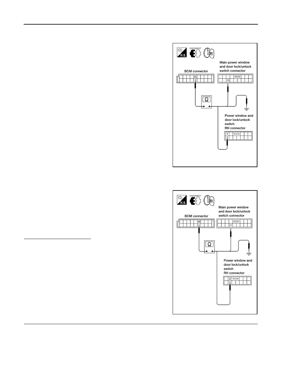
2. Check continuity between BCM connector M19 terminal 45 and main power window and door lock/unlock
switch connector D7 terminal 10 or power window and door lock/unlock switch RH connector D105 termi-
nal 1.
3. Check continuity between BCM connector M19 terminal 45 and
ground.
4. Check continuity between BCM connector M19 terminal 46 and main power window and door lock/unlock
switch LH connector D7 terminal 11 or power window and door lock/unlock switch RH connector D105 ter-
minal 2.
5. Check continuity between BCM connector M19 terminal 46 and
ground.
Is the inspection result normal?
YES
>> GO TO 5
NO
>> Repair or replace harness.
5.
CHECK BCM OUTPUT VOLTAGE
1. Connect BCM.
1 - 45
: Continuity should exist.
10 - 45
: Continuity should exist.
45 - Ground
: Continuity should not exist.
WIIA0630E
2 - 46
: Continuity should exist.
11 - 46
: Continuity should exist.
46 - Ground
: Continuity should not exist.
WIIA0631E