Nissan Frontier. Manual - part 244
DLK-22
< SYSTEM DESCRIPTION >
DIAGNOSIS SYSTEM (BCM)
ACTIVE TEST
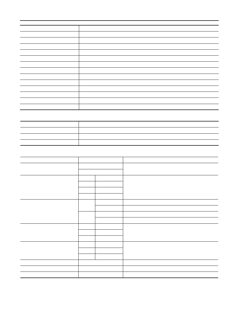
WORK SUPPORT
*: Initial setting
Monitor Item [Unit]
Description
IGN ON SW [On/Off]
Indicates condition of ignition switch ON position.
KEY ON SW [On/Off]
Indicates condition of key switch.
ACC ON SW [On/Off]
Indicates condition of ignition switch ACC position.
KEYLESS LOCK [On/Off]
Indicates condition of lock signal from keyfob.
KEYLESS UNLOCK [On/Off]
Indicates condition of unlock signal from keyfob.
KEYLESS PANIC [On/Off]
Indicates condition of panic signal from keyfob.
DOOR SW-DR [On/Off]
Indicates condition of front door switch LH.
DOOR SW-AS [On/Off]
Indicates condition of front door switch RH.
DOOR SW-RR [On/Off]
Indicates condition of rear door switch RH.
DOOR SW-RL [On/Off]
Indicates condition of rear door switch LH.
CDL LOCK SW [On/Off]
Indicates condition of lock signal from door lock and unlock switch.
CDL UNLOCK SW [On/Off]
Indicates condition of unlock signal from door lock and unlock switch.
KEY CYL LK SW [On/Off]
Indicates condition of lock signal from door key cylinder switch.
Test Item
Description
DOOR LOCK
This test is able to check door lock operation [OTR ULK/DR UNLK/ALL ULK/ALL LCK].
FLASHER
This test is able to check hazard reminder operation [Off/LH/RH].
HORN
This test is able to check horn operation [On].
Support Item
Setting
Description
HORN CHIRP SET
Off
Horn chirp function can be changed in this mode.
On*
HAZARD LAMP SET
MODE4*
Lock and Unlock
Hazard warning lamp function can be changed in this mode.
MODE3
Lock Only
MODE2
Unlock Only
MODE1
OFF
MULTI ANSWER BACK SET
MODE2*
Lock
Hazard warning lamps flash twice and horn does not sound.
Unlock
Hazard warning lamps do not flash and horn does not sound.
MODE1
Lock
Hazard warning lamps flash twice and horn sounds once.
Unlock
Hazard warning lamps flash once and horn does not sound.
AUTO LOCK SET
MODE3
1 min
Auto locking function can be changed in this mode.
MODE2
OFF
MODE1*
5 min
PANIC ALRM SET
MODE3
1.5 sec
Panic alarm operation can be changed in this mode.
MODE2
OFF
MODE1*
0.5 sec
REMO CONT ID REGIST
—
Keyfob ID code can be registered.
REMO CONT ID ERASUR
—
Keyfob ID code can be erased.
REMO CONT ID CONFIR
—
Keyfob ID code registration is displayed.