Nissan Frontier. Manual - part 226


  Index      Nissan     Nissan Frontier (2014 year) - Service and Repair Manual


Search            


Content   ..  224  225  226  227   ..


Nissan Frontier. Manual - part 226


WATER PUMP

CO-51

< REMOVAL AND INSTALLATION >

[VQ40DE]

C

D

E

F

G

H

I

J

K

L

M

A

CO

N

P

O

3. Remove coolant reservoir hose from the radiator.
4. Remove engine cooling fan (Motor driven type). Refer to 

CO-48, "Removal and Installation (Motor driven

type)"

5. Remove engine cooling fan (Crankshaft driven type) and fan bracket. Refer to 

CO-47, "Removal and

Installation (Crankshaft driven type)"

.

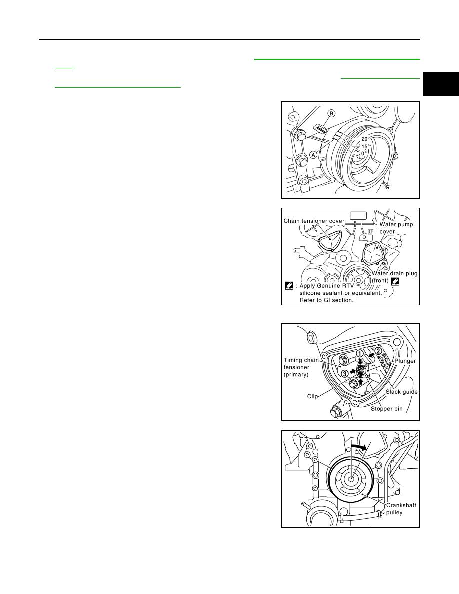
6. Set No. 1 cylinder at TDC.

• Rotate crankshaft pulley clockwise to align timing mark (A)

(grooved line without color) with timing indicator (B).

7. Remove chain tensioner cover and water pump cover from front

timing chain case, using Tool.

8. Remove timing chain tensioner (primary) as follows:
a. Loosen clip of timing chain tensioner (primary), and release

plunger stopper (1).

b. Insert plunger into tensioner body by pressing slack guide (2).
c. Keep slack guide pressed and hold plunger in by pushing stop-

per pin through the tensioner body hole and plunger groove (3).

d. Turn crankshaft pulley clockwise so that timing chain on the tim-

ing chain tensioner (primary) side is loose.

AWBIA0719ZZ

Tool number

: KV10111100 (J-37228)

PBIC2662E

PBIC2835E

PBIC2834E

CO-52

< REMOVAL AND INSTALLATION >

[VQ40DE]

WATER PUMP

e. Remove bolts and remove timing chain tensioner (primary).

CAUTION:

Be careful not to drop bolts inside timing chain case.

9. Remove water pump as follows:
a. Remove three water pump bolts. Secure a gap between water

pump gear and timing chain, by turning crankshaft pulley coun-

terclockwise until timing chain looseness on water pump

sprocket becomes maximum. 

b. Screw M8 bolts [pitch: 1.25 mm (0.049 in) length: approx. 50

mm (1.97 in)] into water pump upper and lower bolt holes until

they reach timing chain case. Then, alternately tighten each bolt

for a half turn, and pull out water pump.

CAUTION:

• Place a suitable shop cloth below the water pump hous-

ing to prevent any engine coolant from dripping into the

timing chain case.

• Pull water pump straight out while preventing vane from

contacting socket in installation area.

• Remove water pump without causing sprocket to contact

timing chain.

c.

Remove M8 bolts and O-rings from water pump.

CAUTION:

• Do not disassemble water pump.

• Do not reuse O-rings.

INSPECTION AFTER REMOVAL

• Check for badly rusted or corroded water pump body assembly.

• Check for rough operation due to excessive end play.

• Replace water pump, if necessary.

INSTALLATION

1. Install new O-rings to water pump.

CAUTION:

Do not reuse O-rings.

NOTE:

PBIC2836E

PBIC2863E

JLC357B

SLC943A

WATER PUMP

CO-53

< REMOVAL AND INSTALLATION >

[VQ40DE]

C

D

E

F

G

H

I

J

K

L

M

A

CO

N

P

O

• Apply engine oil to O-rings.

• Locate O-ring with white paint mark to engine front side.

2. Hold timing chain to the side (

) and install water pump (

).

CAUTION:

Do not allow timing chain case to pinch O-rings when

installing water pump.

• Make sure that timing chain and water pump sprocket are

engaged.

• Tighten water pump bolts alternately and evenly.

3. Remove dust and foreign material completely from installation area of timing chain tensioner (primary)

and rear timing chain case.

4. Turn crankshaft pulley approximately 20

° clockwise so that tim-

ing chain on the timing chain tensioner (primary) side is loose.

5. Install timing chain tensioner (primary) with its stopper pin inserted.

CAUTION:

Be careful not to drop bolts inside timing chain case.

6. Remove stopper pin.

• Make sure again that timing chain and water pump sprocket

are engaged.

7. Install chain tensioner cover and water pump cover.

PBIC2837E

PBIC1058E

PBIC0848E

PBIC2838E

CO-54

< REMOVAL AND INSTALLATION >

[VQ40DE]

WATER PUMP

a. Before installing, remove all traces of old liquid gasket from mat-

ing surface of water pump cover and chain tensioner cover

using scraper. Also remove traces of old liquid gasket from the

mating surface of front timing chain case.

b. Apply a continuous bead of liquid gasket, to mating surface of

chain tensioner and water pump cover, using suitable tool.

Use Genuine RTV Silicone Sealant or equivalent. Refer to

GI-21, "Recommended Chemical Products and Sealants"

.

CAUTION:

• Installation should be done within 5 minutes after apply-

ing liquid gasket.

• Do not fill the engine with oil for at least 30 minutes after

the components are installed to allow the sealant to cure.

c.

Tighten bolts to specified torque. Refer to 

CO-50, "Exploded

View"

.

8. Install water drain plug (front) (1) on water pump side of cylinder

block.

• Apply liquid gasket to the thread of water drain plug (front).

Use Genuine RTV Silicone Sealant or equivalent. Refer to

GI-21, "Recommended Chemical Products and Sealants"

.

9. Installation of the remaining components is in the reverse order of removal.

• After installation refill engine coolant and check for leaks. Refer to 

CO-40, "Changing Engine Coolant"

and 

CO-39, "System Inspection"

.

CAUTION:

Do not spill coolant in the engine compartment. Use a shop cloth to absorb coolant.

• After starting engine, let idle for three minutes, then rev engine up to 3,000 rpm under no load to purge

air from the high-pressure chamber of the chain tensioner. The engine may produce a rattling noise.

This indicates that air still remains in the chamber and is not a matter of concern.

INSPECTION AFTER INSTALLATION

• Check for engine coolant leaks. Refer to 

CO-39, "System Inspection"

.

• Start and warm up engine. Visually check for engine coolant leaks. Repair as necessary.

SLC446B

PBIC2663E

Water drain plug (front)

: 9.8 N·m (1.0 kg-m, 87 in-lb)

ALBIA0679ZZ


Content   ..  224  225  226  227   ..