Nissan Frontier. Manual - part 212
CLUTCH DISC, CLUTCH COVER
CL-21
< UNIT REMOVAL AND INSTALLATION >
C
E
F
G
H
I
J
K
L
M
A
B
CL
N
O
P
• Broken thrust ring will make a clinking sound when cover is shaken up and down.
• If a trace of burn or discoloration is found on the clutch cover pressure plate to clutch disc contact surface,
repair the surface with emery paper. If surface is damaged or distorted, replace the assembly.
Flywheel
• Check contact surface of flywheel for slight burns or discoloration.
If any are found, repair flywheel with emery paper.
• Check the flywheel runout. Refer to
5M/T : Adjustment after Installation
INFOID:0000000009478224
ADJUSTMENT AFTER INSTALLATION
Clutch Cover
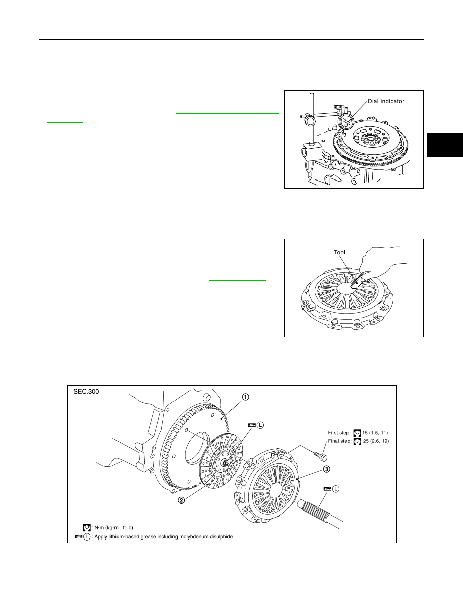
With the clutch cover installed on the vehicle, check the diaphragm
spring toe height for unevenness. If unevenness exceeds the limit,
adjust the diaphragm spring toe height using Tool.
6M/T
6M/T : Exploded View
INFOID:0000000009478225
PBIC2168E
Uneven limit of diaphragm
spring toe height
: Refer to
.
Tool number
: ST20050240 ( — )
PCIB0276E
1.
Flywheel
2.
Clutch disc
3.
Clutch cover
WCIA0522E