Nissan Frontier. Manual - part 209
CLUTCH PEDAL
CL-9
< REMOVAL AND INSTALLATION >
C
E
F
G
H
I
J
K
L
M
A
B
CL
N
O
P
REMOVAL AND INSTALLATION
CLUTCH PEDAL
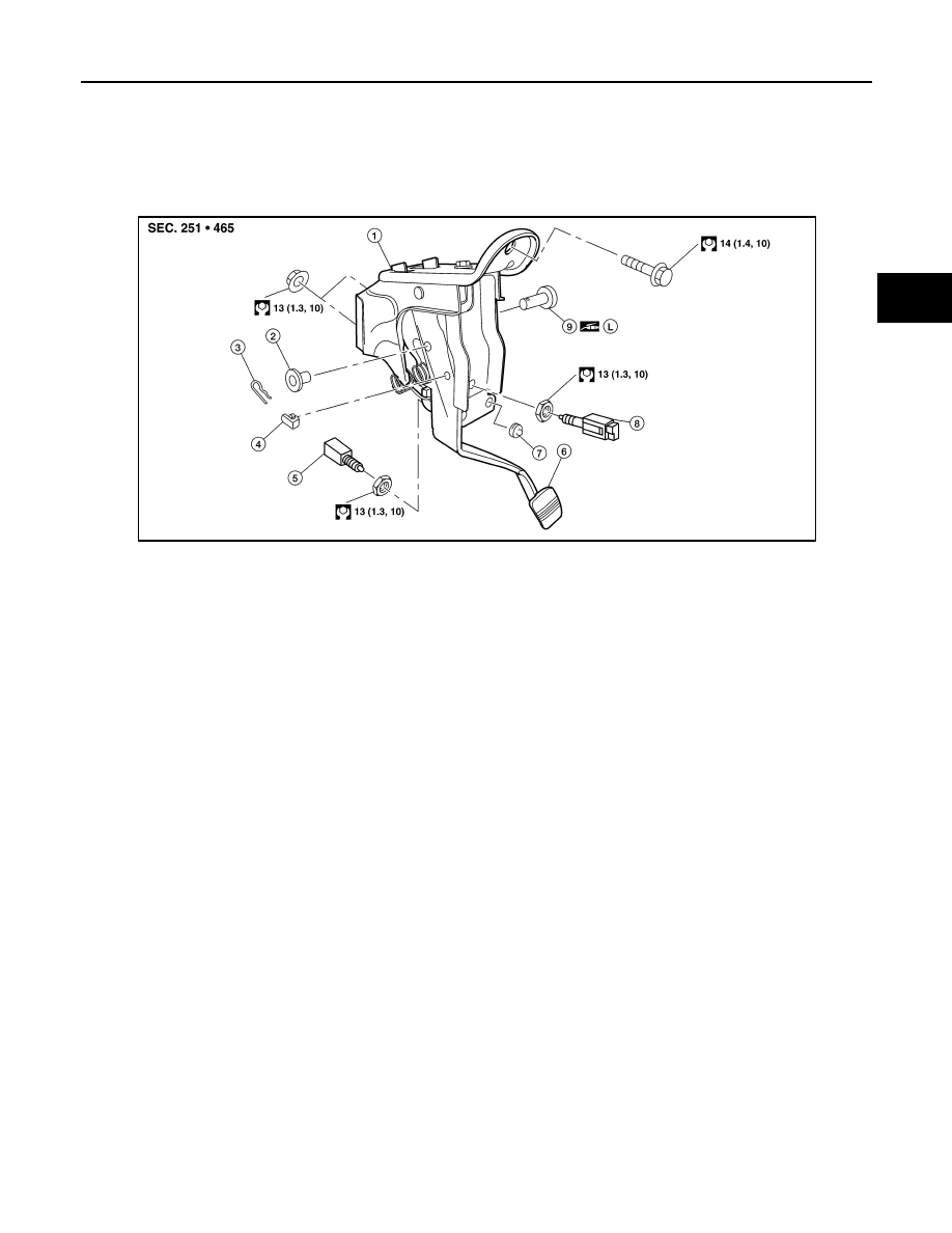
Exploded View
INFOID:0000000009478205
Removal and Installation
INFOID:0000000009478206
REMOVAL
1. Remove the clutch pedal bracket nuts from inside the engine compartment.
2. Disconnect the clutch interlock switch and ASCD clutch switch (if equipped), then remove the harness
from the pedal assembly.
3. Remove the snap pin and clevis pin.
4. Remove the pedal bracket bolt and then remove the clutch pedal assembly.
INSTALLATION
Installation is in the reverse order of removal.
NOTE:
Tighten the pedal stopper bolt lock nut or ASCD clutch switch lock nut to the specified torque after installing
the clutch pedal assembly in the vehicle and adjusting the pedal free play.
Inspection
INFOID:0000000009478207
INSPECTION AFTER REMOVAL
• Inspect the clutch pedal for bends, damage, or cracked welds. Replace if necessary.
• Make sure that the assist spring and return spring have not lost their tension. Replace if necessary.
1.
Bracket
2.
Bushing
3.
Snap pin
4.
Pedal stopper rubber
5.
Clutch interlock switch
6.
Clutch pedal
7.
Stopper rubber
8.
ASCD clutch switch (if equipped)
9.
Pedal stopper bolt
10. Clevis pin
L.
Apply wheel bearing grease
AWDIA1131ZZ