Nissan Frontier. Manual - part 167


  Index      Nissan     Nissan Frontier (2014 year) - Service and Repair Manual


Search            


Content   ..  165  166  167  168   ..


Nissan Frontier. Manual - part 167


BRC-196

< DTC/CIRCUIT DIAGNOSIS >

[TYPE 2]

HILL DESCENT CONTROL SWITCH

HILL DESCENT CONTROL SWITCH

Description

INFOID:0000000009479505

The hill descent control switch activates (turn ON) the hill descent control function when the hill descent con-

trol switch is pressed.

Component Function Check

INFOID:0000000009479506

1.

CHECK HILL DESCENT CONTROL SWITCH OPERATION

Turn ON/OFF the hill descent control switch and check that the hill descent control indicator lamp in the com-

bination meter turns ON/OFF correctly.

Is the inspection result normal?

YES

>> Inspection End

NO

>> Go to diagnosis procedure. Refer to 

BRC-196, "Diagnosis Procedure"

.

Diagnosis Procedure

INFOID:0000000009479507

Regarding Wiring Diagram information, refer to 

BRC-213, "Wiring Diagram - VDC WITH HILL DESCENT

CONTROL/HILL START ASSIST"

.

1.

CHECK HILL DESCENT CONTROL SWITCH

Perform the hill descent control switch component inspection. Refer to 

BRC-197, "Component Inspection"

.

Is the inspection result normal?

YES

>> GO TO 2

NO

>> Replace hill descent control switch.

2.

CHECK HILL DESCENT CONTROL SWITCH HARNESS

1. Disconnect ABS actuator and electric unit (control unit) connector.

2. Check continuity between ABS actuator and electric unit (control unit) connector E127 (A) terminal 25 and

hill descent control switch connector M155 (B) terminal 2.

3. Check continuity between ABS actuator and electric unit (control unit) connector E127 (A) terminal 25 and

ground.

Is the inspection result normal?

YES

>> GO TO 3

NO

>> Repair or replace harness.

3.

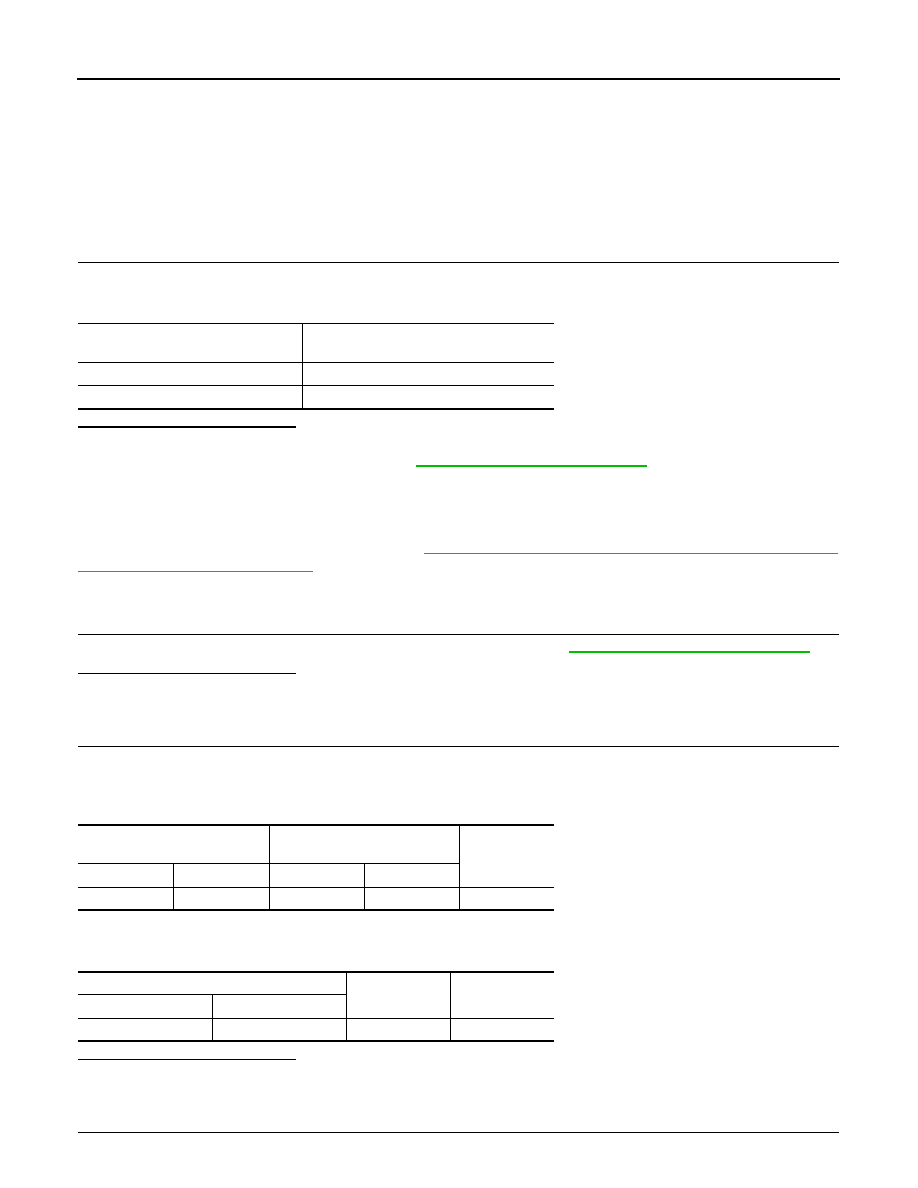
CHECK HILL DESCENT CONTROL SWITCH GROUND

Condition

Hill descent control indicator lamp illumina-

tion status

Hill descent control switch: ON

ON

Hill descent control switch: OFF

OFF

ABS actuator and electric unit 

(control unit)

Hill descent control switch

Continuity

Connector

Terminal

Connector

Terminal

E127 (A)

25

M155 (B)

2

Yes

ABS actuator and electric unit (control unit)

Continuity

Connector

Terminal

E127 (A)

25

Ground

No

HILL DESCENT CONTROL SWITCH

BRC-197

< DTC/CIRCUIT DIAGNOSIS >

[TYPE 2]

C

D

E

G

H

I

J

K

L

M

A

B

BRC

N

O

P

Check continuity between hill descent control switch connector

M155 terminal 1 and ground.

Is the inspection result normal?

YES

>> GO TO 4

NO

>> Repair or replace harness.

4.

CHECK COMBINATION METER

Check if the indication and operation of combination meter are normal. Refer to 

MWI-25, "Diagnosis Descrip-

tion"

.

Is the inspection result normal?

YES

>> Replace ABS actuator and electric unit (control unit). Refer to 

BRC-236, "Removal and Installa-

tion"

.

NO

>> Replace combination meter. Refer to 

MWI-90, "Removal and Installation"

.

Component Inspection

INFOID:0000000009479508

1.

CHECK HILL DESCENT CONTROL SWITCH

1. Turn ignition switch OFF.

2. Disconnect hill descent control switch connector.

3. Check continuity between hill descent control switch terminals.

Is the inspection result normal?

YES

>> Inspection End

NO

>> Replace hill descent control switch.

Special Repair Requirement

INFOID:0000000009479509

1.

ADJUSTMENT OF STEERING ANGLE SENSOR NEUTRAL POSITION

Always perform neutral position adjustment for the steering angle sensor when replacing the ABS actuator

and electric unit (control unit). Refer to 

BRC-124, "ADJUSTMENT OF STEERING ANGLE SENSOR NEU-

TRAL POSITION : Description"

.

>> GO TO 2

2.

CALIBRATION OF DECEL G SENSOR

Always perform calibration of decel G sensor when replacing the ABS actuator and electric unit (control unit).

Refer to 

BRC-125, "CALIBRATION OF DECEL G SENSOR : Description"

.

>> END

Hill descent control switch

Continuity

Connector

Terminal

M155

1

Ground

Yes

AWFIA0220ZZ

Hill descent control

switch terminals

Condition

Continuity

− 2

Hill descent control switch is ON.

Yes

Hill descent control switch is OFF.

No

BRC-198

< DTC/CIRCUIT DIAGNOSIS >

[TYPE 2]

VDC OFF SWITCH

VDC OFF SWITCH

Description

INFOID:0000000009479510

VDC OFF switch can deactivate (turn OFF) the VDC/TCS function by pressing the VDC OFF switch.

Component Function Check

INFOID:0000000009479511

1.

CHECK VDC OFF SWITCH OPERATION

Press and release the VDC OFF switch, then press and release the VDC OFF switch again and check that the

VDC OFF indicator lamp in the combination meter turns ON/OFF correctly.

Is the inspection result normal?

YES

>> Inspection End

NO

>> Go to diagnosis procedure. Refer to 

BRC-198, "Diagnosis Procedure"

.

Diagnosis Procedure

INFOID:0000000009479512

Regarding Wiring Diagram information, refer to 

BRC-213, "Wiring Diagram - VDC WITH HILL DESCENT

CONTROL/HILL START ASSIST"

.

1.

CHECK VDC OFF SWITCH

Perform the VDC OFF switch component inspection. Refer to 

BRC-199, "Component Inspection"

.

Is the inspection result normal?

YES

>> GO TO 2

NO

>> Replace VDC OFF switch.

2.

CHECK VDC OFF SWITCH HARNESS

1. Disconnect ABS actuator and electric unit (control unit) connector.

2. Check continuity between ABS actuator and electric unit (control unit) connector E127 (A) terminal 6 and

VDC OFF switch connector M154 (B) terminal 1.

3. Check continuity between ABS actuator and electric unit (control unit) connector E127 (A) terminal 6 and

ground.

Is the inspection result normal?

YES

>> GO TO 3

NO

>> Repair or replace harness.

3.

CHECK VDC OFF SWITCH GROUND

Condition

VDC OFF indicator lamp illumination status

VDC OFF switch: pressed and released

ON

VDC OFF switch: pressed and released

OFF

ABS actuator and electric unit 

(control unit)

VDC OFF switch

Continuity

Connector

Terminal

Connector

Terminal

E127 (A)

6

M154 (B)

1

Yes

ABS actuator and electric unit (control unit)

Continuity

Connector

Terminal

E127 (A)

6

Ground

No

VDC OFF SWITCH

BRC-199

< DTC/CIRCUIT DIAGNOSIS >

[TYPE 2]

C

D

E

G

H

I

J

K

L

M

A

B

BRC

N

O

P

Check continuity between VDC OFF switch connector M154 terminal

2 and ground.

Is the inspection result normal?

YES

>> GO TO 4

NO

>> Repair or replace harness.

4.

CHECK COMBINATION METER

Check if the indication and operation of combination meter are normal. Refer to 

MWI-25, "Diagnosis Descrip-

tion"

.

Is the inspection result normal?

YES

>> Replace ABS actuator and electric unit (control unit). Refer to 

BRC-236, "Removal and Installa-

tion"

.

NO

>> Replace combination meter. Refer to 

MWI-90, "Removal and Installation"

.

Component Inspection

INFOID:0000000009479513

1.

CHECK VDC OFF SWITCH

1. Turn ignition switch OFF.

2. Disconnect VDC OFF switch connector.

3. Check continuity between VDC OFF switch terminals.

Is the inspection result normal?

YES

>> Inspection End

NO

>> Replace VDC OFF switch.

Special Repair Requirement

INFOID:0000000009479514

1.

ADJUSTMENT OF STEERING ANGLE SENSOR NEUTRAL POSITION

Always perform neutral position adjustment for the steering angle sensor when replacing the ABS actuator

and electric unit (control unit). Refer to 

BRC-124, "ADJUSTMENT OF STEERING ANGLE SENSOR NEU-

TRAL POSITION : Description"

.

>> GO TO 2

2.

CALIBRATION OF DECEL G SENSOR

Always perform calibration of decel G sensor when replacing the ABS actuator and electric unit (control unit).

Refer to 

BRC-125, "CALIBRATION OF DECEL G SENSOR : Description"

.

>> END

VDC OFF switch

Continuity

Connector

Terminal

M154

2

Ground

Yes

AWFIA0031ZZ

VDC OFF switch terminals

Condition

Continuity

− 2

VDC OFF switch pressed.

Yes

VDC OFF switch released.

No


Content   ..  165  166  167  168   ..