Nissan Frontier. Manual - part 162
BRC-176
< DTC/CIRCUIT DIAGNOSIS >
[TYPE 2]
C1121, C1123, C1125, C1127 OUT ABS SOL
C1121, C1123, C1125, C1127 OUT ABS SOL
Description
INFOID:0000000009479462
The solenoid valve increases, holds or decreases the fluid pressure of each brake caliper according to the sig-
nals transmitted by the ABS actuator and electric unit (control unit).
DTC Logic
INFOID:0000000009479463
DTC DETECTION LOGIC
DTC CONFIRMATION PROCEDURE
1.
CHECK SELF-DIAGNOSIS RESULTS
Check the self-diagnosis results.
Is above displayed on the self-diagnosis display?
YES
>> Proceed to diagnosis procedure. Refer to
BRC-176, "Diagnosis Procedure"
.
NO
>> Inspection End
Diagnosis Procedure
INFOID:0000000009479464
Regarding Wiring Diagram information, refer to
BRC-213, "Wiring Diagram - VDC WITH HILL DESCENT
1.
CONNECTOR INSPECTION
1. Turn ignition switch OFF.
2. Disconnect ABS actuator and electric unit (control unit) connector.
3. Check terminals for deformation, disconnection, looseness, and so on. If any malfunction is found, repair
or replace terminals.
4. Reconnect connectors and then perform the self-diagnosis. Refer to
.
Is any item indicated on the self-diagnosis display?
YES
>> GO TO 2
NO
>> Poor connection of connector terminals. Repair or replace connector.
2.
CHECK SOLENOID, VDC SWITCH-OVER VALVE AND ACTUATOR RELAY POWER SUPPLY CIRCUIT
1. Turn ignition switch OFF.
2. Disconnect ABS actuator and electric unit (control unit) connector.
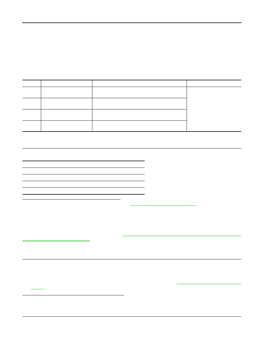
DTC
Display item
Malfunction detected condition
Possible cause
C1121
FR LH OUT ABS SOL
When the control unit detects a malfunction in the front
LH outlet solenoid circuit.
• ABS actuator and electric unit
(control unit)
C1123
FR RH OUT ABS SOL
When the control unit detects a malfunction in the front
RH outlet solenoid circuit.
C1125
RR LH OUT ABS SOL
When the control unit detects a malfunction in the rear LH
outlet solenoid circuit.
C1127
RR RH OUT ABS SOL
When the control unit detects a malfunction in the rear
RH outlet solenoid circuit.
Self-diagnosis results
FR LH OUT ABS SOL
FR RH OUT ABS SOL
RR LH OUT ABS SOL
RR RH OUT ABS SOL