Content .. 1305 1306 1307 1308 ..
Nissan Frontier. Manual - part 1307
WCS
KEY SWITCH SIGNAL CIRCUIT
WCS-23
< DTC/CIRCUIT DIAGNOSIS >
C
D
E
F
G
H
I
J
K
L
M
B
A
O
P
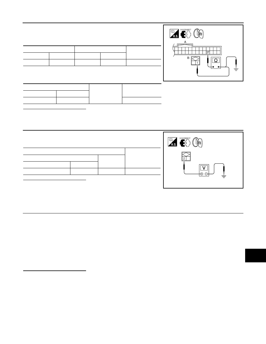
1. Disconnect BCM connector M18 and key switch connector.
2. Check continuity between BCM harness connector M18 (A) ter-
minal 37 and key switch harness connector M27 (B) terminal 1.
3. Check continuity between BCM harness connector M18 (A) ter-
minal 37 and ground.
Is the inspection result normal?
YES
>> GO TO 4
NO
>> Repair or replace harness.
4.
CHECK KEY SWITCH POWER SUPPLY CIRCUIT
Check voltage between key switch harness connector M27 terminal
2 and ground.
Is the inspection result normal?
YES
>> Replace key switch.
NO
>> Repair or replace harness.
Component Inspection
INFOID:0000000009478009
1.
CHECK KEY SWITCH
1. Turn ignition switch OFF.
2. Disconnect key switch.
3. Check continuity between key switch terminals 1 and 2.
Is the inspection result normal?
YES
>> Inspection End.
NO
>> Replace key switch.
BCM
Key switch
Continuity
Connector
Terminal
Connector
Terminal
M18 (A)
37
M27 (B)
1
Yes
BCM
Ground
Continuity
Connector
Terminal
M18 (A)
37
No
WKIA4102E
Terminals
Voltage
(Approx.)
(+)
(
−)
Key switch
Terminal
M27
2
Ground
Battery voltage
WKIA4103E
1 – 2
When key is inserted
into key cylinder
: Continuity should exist.
When key is removed
from key cylinder
: Continuity should not exist.