Nissan Frontier. Manual - part 1292


  Index      Nissan     Nissan Frontier (2014 year) - Service and Repair Manual


Search            


Content   ..  1290  1291  1292  1293   ..


Nissan Frontier. Manual - part 1292


ASSEMBLY

TM-379

< UNIT DISASSEMBLY AND ASSEMBLY >

[5AT: RE5R05A]

C

E

F

G

H

I

J

K

L

M

A

B

TM

N

O

P

Assembly (2)

INFOID:0000000009480706

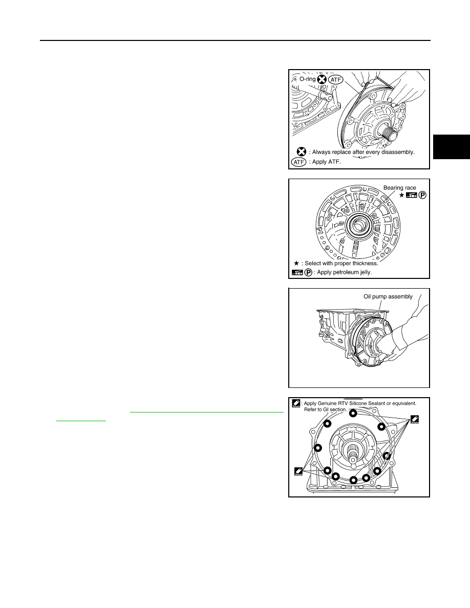
1. Install O-ring to oil pump assembly.

CAUTION:

• Do not reuse O-ring.

• Apply ATF to O-ring.

2. Install bearing race to oil pump assembly.

CAUTION:

Apply petroleum jelly to bearing race.

3. Install oil pump assembly in transmission case.

CAUTION:

Apply ATF to oil pump bearing.

4. Apply recommended sealant (Genuine RTV Silicone Sealant or

equivalent. Refer to 

GI-21, "Recommended Chemical Products

and Sealants"

.) to oil pump assembly as shown.

CAUTION:

Completely remove all moisture, oil, old sealant and any

foreign material from the oil pump bolts and oil pump bolt

mating surfaces.

SCIA5172E

SCIA6529E

SCIA2811E

SCIA5321E

TM-380

< UNIT DISASSEMBLY AND ASSEMBLY >

[5AT: RE5R05A]

ASSEMBLY

5. Tighten oil pump bolts to specified torque.

CAUTION:

Apply ATF to oil pump bushing.

6. Install O-ring to input clutch assembly.

CAUTION:

• Do not reuse O-ring.

• Apply ATF to O-ring.

7. Install converter housing to transmission case and tighten bolts

to specified torque.

CAUTION:

Do not reuse self-sealing bolt (A).

8. Make sure that brake band (1) does not close input speed sen-

sor hole (A).

9. Connect TCM connector (1) and transmission range switch con-

nector (2).

Oil pump bolts

: 48 N·m (4.9 kg-m, 35 ft-lb)

SCIA2300E

SCIA5011E

Converter housing bolt

: 52 N·m (5.3 kg-m, 38 ft-lb)

Self-sealing bolt (A)

: 61 N·m (6.2 kg-m, 45 ft-lb)

WCIA0662E

JSDIA1318ZZ

JSDIA1317ZZ

ASSEMBLY

TM-381

< UNIT DISASSEMBLY AND ASSEMBLY >

[5AT: RE5R05A]

C

E

F

G

H

I

J

K

L

M

A

B

TM

N

O

P

10. Install A/T assembly harness connector to control valve with

TCM.

11. Connect TCM connectors.

12. Install O-ring to A/T assembly harness connector.

CAUTION:

• Do not reuse O-ring.

• Apply ATF to O-ring.

13. Install new O-ring (1) in plug (2).

CAUTION:

• Do not reuse O-ring.

• Apply ATF to O-ring.

• O-ring should be free of contamination.

14. Install plug (2) to bracket (1).

SCIA5450E

SCIA5447E

SCIA5155E

JSDIA1313ZZ

JSDIA1312ZZ

TM-382

< UNIT DISASSEMBLY AND ASSEMBLY >

[5AT: RE5R05A]

ASSEMBLY

15. Install plug (1) [with bracket (2)] to control valve with TCM and

tighten bolt (

) to specified torque.

CAUTION:

Adjust bolt hole of bracket to bolt hole of control valve.

16. Install control valve with TCM in transmission case.

CAUTION:

• Make sure that input speed sensor is securely installed

into input speed sensor hole (A).

• Hang down output speed sensor harness toward outside

so as not to disturb installation of control valve with TCM.

• Adjust A/T assembly harness connector of control valve

with TCM to terminal hole of transmission case.

• Assemble it so that manual valve cutout is engaged with

manual plate projection.

17. Install bolts (A), (B) and (C) to control valve with TCM.

18. Tighten bolt (A), (B) and (C) temporarily to prevent dislocation.

After that tighten them in order (A 

→ B → C), and then tighten

other bolts.

Bracket bolt

: 7.9 N·m (0.81 kg-m, 70 in-lb)

JSDIA1311ZZ

1

: Brake band

JSDIA1318ZZ

SCIA5035E

: Front

Bolt symbol

Length mm (in)

Number of bolts

A

42 (1.65)

5

B

55 (2.17)

6

C

40 (1.57)

1

SCIA8077E

: Front

Bolt symbol

A

B

C

Number of bolts

5

6

1

Length mm (in)

42 (1.65)

55 (2.17)

40 (1.57)

SCIA8078E


Content   ..  1290  1291  1292  1293   ..