Nissan Frontier. Manual - part 1284


  Index      Nissan     Nissan Frontier (2014 year) - Service and Repair Manual


Search            


Content   ..  1282  1283  1284  1285   ..


Nissan Frontier. Manual - part 1284


FRONT SUN GEAR, 3RD ONE-WAY CLUTCH

TM-347

< UNIT DISASSEMBLY AND ASSEMBLY >

[5AT: RE5R05A]

C

E

F

G

H

I

J

K

L

M

A

B

TM

N

O

P

Front Sun Gear Snap Ring

• Check for deformation, fatigue or damage.

CAUTION:

If necessary, replace the snap ring.

Front Sun Gear

• Check for deformation, fatigue or damage.

CAUTION:

If necessary, replace the front sun gear.

ASSEMBLY

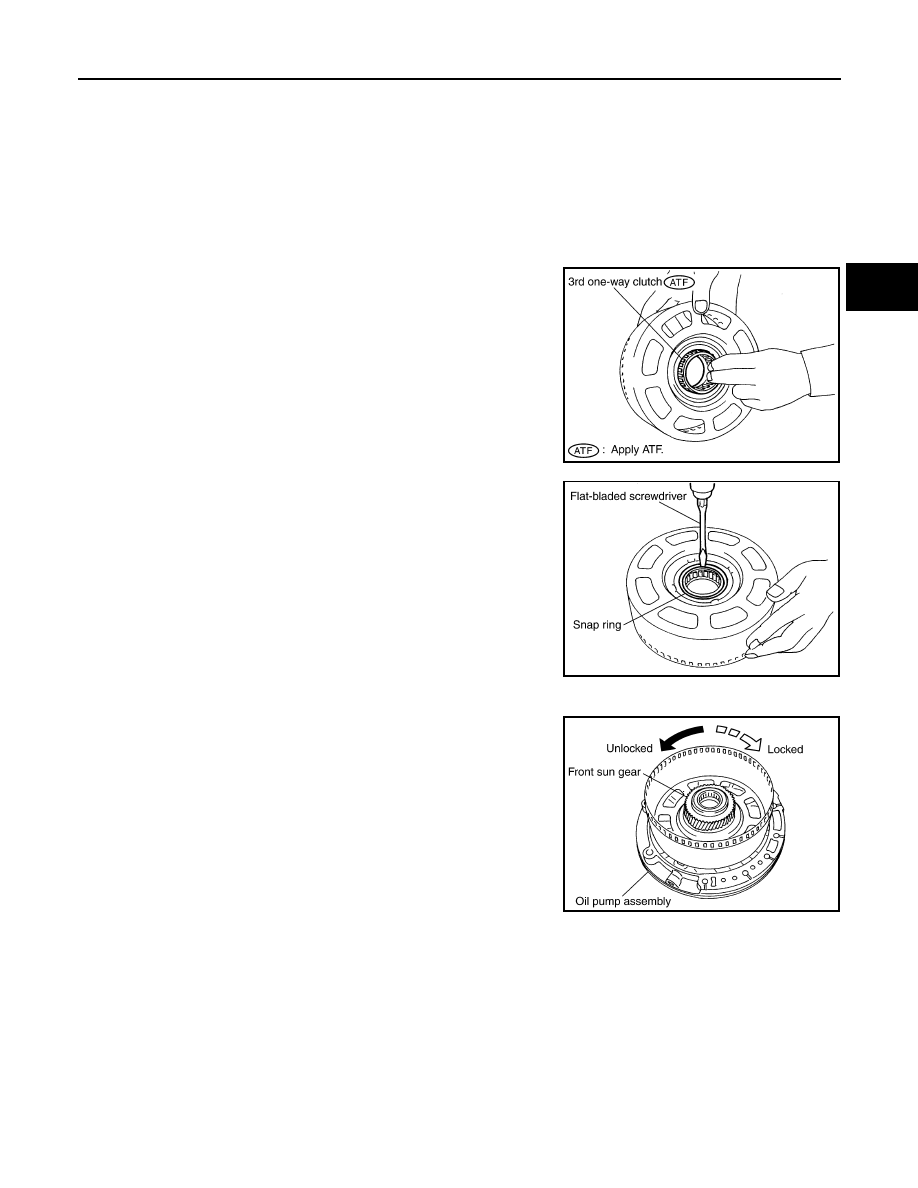
1. Install 3rd one-way clutch in front sun gear.

CAUTION:

Apply ATF to 3rd one-way clutch.

2. Install snap ring in front sun gear using suitable tool.

3. Check operation of 3rd one-way clutch.
a. Hold oil pump assembly and turn front sun gear.
b. Check 3rd one-way clutch for correct locking and unlocking

directions.

CAUTION:

If not as shown, check installation direction of 3rd one-way

clutch.

SCIA3111E

SCIA3110E

SCIA3131E

TM-348

< UNIT DISASSEMBLY AND ASSEMBLY >

[5AT: RE5R05A]

FRONT CARRIER, INPUT CLUTCH, REAR INTERNAL GEAR

FRONT CARRIER, INPUT CLUTCH, REAR INTERNAL GEAR

Front Carrier, Input Clutch, Rear Internal Gear

INFOID:0000000009480700

COMPONENTS

DISASSEMBLY

1.

Seal ring

2.

O-ring

3.

Needle bearing

4.

Bearing race

5.

Front carrier assembly

6.

Needle bearing

7.

Snap ring

8.

Snap ring

9.

Retaining plate

10. Driven plate

11. Input clutch drum

12. Drive plate

Refer to 

GI-4, "Component"

 for symbols in the figure.

SCIA6734E

FRONT CARRIER, INPUT CLUTCH, REAR INTERNAL GEAR

TM-349

< UNIT DISASSEMBLY AND ASSEMBLY >

[5AT: RE5R05A]

C

E

F

G

H

I

J

K

L

M

A

B

TM

N

O

P

1. Compress snap ring using suitable tools.
2. Remove front carrier assembly and input clutch assembly from

rear internal gear.

3. Remove front carrier assembly from input clutch assembly.

a. Remove bearing race from front carrier assembly.

b. Remove needle bearing from front carrier assembly.

c. Remove snap ring from front carrier assembly.

CAUTION:

Do not expand snap ring excessively.

4. Disassemble input clutch assembly.
a. Remove O-ring and seal rings from input clutch assembly.

SCIA5339E

SCIA2847E

SCIA5233E

SCIA5476E

SCIA5235E

TM-350

< UNIT DISASSEMBLY AND ASSEMBLY >

[5AT: RE5R05A]

FRONT CARRIER, INPUT CLUTCH, REAR INTERNAL GEAR

b. Remove needle bearing from input clutch assembly.

c.

Remove snap ring from input clutch drum using suitable tools.

d. Remove drive plates, driven plates and retaining plate from input

clutch drum.

INSPECTION

Front Carrier Snap Ring

• Check for deformation, fatigue or damage.

CAUTION:

If necessary, replace the snap ring.

Input Clutch Snap Ring

• Check for deformation, fatigue or damage.

CAUTION:

If necessary, replace the input clutch assembly.

Input Clutch Drum

• Check for deformation, fatigue or damage or burns.

CAUTION:

If necessary, replace the input clutch assembly.

Input Clutch Drive Plates

• Check facing for burns, cracks or damage.

CAUTION:

If necessary, replace the input clutch assembly.

Input Clutch Retaining Plate and Driven Plates

• Check facing for burns, cracks or damage.

CAUTION:

If necessary, replace the input clutch assembly.

Front Carrier

• Check for deformation, fatigue or damage.

CAUTION:

If necessary, replace the front carrier assembly.

Rear Internal Gear

• Check for deformation, fatigue or damage.

CAUTION:

If necessary, replace the rear internal gear assembly.

ASSEMBLY

1. Install input clutch.

SCIA2853E

SCIA2864E


Content   ..  1282  1283  1284  1285   ..