Content .. 1244 1245 1246 1247 ..
Nissan Frontier. Manual - part 1246
P1705 TP SENSOR
TM-195
< DTC/CIRCUIT DIAGNOSIS >
[5AT: RE5R05A]
C
E
F
G
H
I
J
K
L
M
A
B
TM
N
O
P
P1705 TP SENSOR
Description
INFOID:0000000009480573
Electric throttle control actuator consists of throttle control motor, accelerator pedal position sensor, throttle
position sensor, etc. The actuator sends a signal to the ECM, and ECM sends signals to TCM with CAN com-
munication.
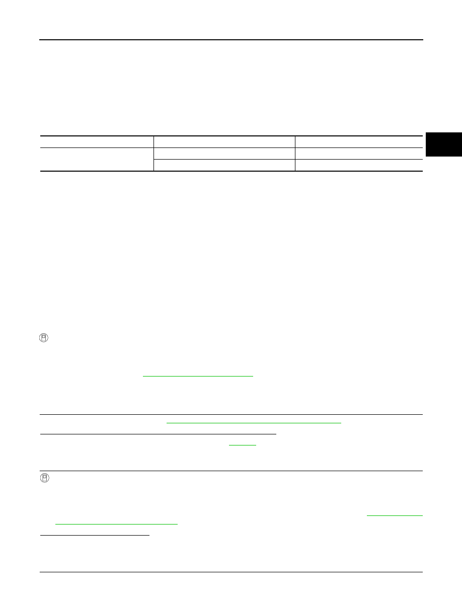
CONSULT Reference Value in Data Monitor Mode
INFOID:0000000009480574
On Board Diagnosis Logic
INFOID:0000000009480575
• This is not an OBD-II self-diagnostic item.
• Diagnostic trouble code “P1705” with CONSULT or 15th judgment flicker without CONSULT is detected
when TCM does not receive the proper accelerator pedal position signals (input by CAN communication)
from ECM.
Possible Cause
INFOID:0000000009480576
Harness or connectors
(The sensor circuit is open or shorted.)
DTC Confirmation Procedure
INFOID:0000000009480577
NOTE:
If “DTC Confirmation Procedure” has been previously performed, always turn ignition switch “OFF”
and wait at least 10 seconds before performing the next test.
After the repair, perform the following procedure to confirm the malfunction is eliminated.
WITH CONSULT
1. Turn ignition switch “ON”. (Do not start engine.)
2. Select “DATA MONITOR” mode for "TRANSMISSION" with CONSULT.
3. Start engine and let it idle for 1 second.
4. If DTC is detected, go to
.
Diagnosis Procedure
INFOID:0000000009480578
1.
CHECK CAN COMMUNICATION LINE
Perform the self-diagnosis. Refer to
TM-157, "CONSULT Function (TRANSMISSION)"
.
Is a malfunction in the CAN communication indicated in the results?
YES
>> Check CAN communication line. Refer to
NO
>> GO TO 2.
2.
CHECK DTC WITH TCM
With CONSULT
1. Turn ignition switch ON. (Do not start engine.)
2. Select “ECU INPUT SIGNALS” in “DATA MONITOR” mode for “TRANSMISSION” with CONSULT.
3. Depress accelerator pedal and read out the value of “ACCELE POSI”.
4. Select “SELF-DIAG RESULTS” mode for “TRANSMISSION” with CONSULT. Refer to
.
Is the inspection result normal?
YES
>> GO TO 4.
NO
>> GO TO 3.
3.
CHECK DTC WITH ECM
Item name
Condition
Display value (Approx.)
ACCELE POSI
Released accelerator pedal.
0.0/8
Fully depressed accelerator pedal.
8/8