Nissan Frontier. Manual - part 1227


  Index      Nissan     Nissan Frontier (2014 year) - Service and Repair Manual


Search            


Content   ..  1225  1226  1227  1228   ..


Nissan Frontier. Manual - part 1227


GEAR COMPONENTS

TM-119

< UNIT DISASSEMBLY AND ASSEMBLY >

[6MT: FS6R31A]

C

E

F

G

H

I

J

K

L

M

A

B

TM

N

O

P

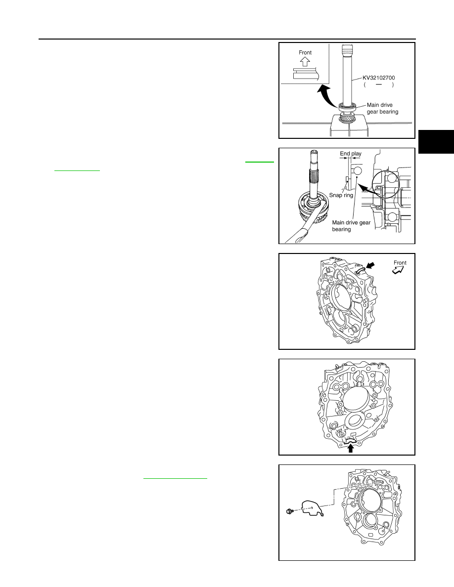
a. Press in main drive gear bearing using Tool.

CAUTION:

Be careful with the orientation main drive gear bearing.

b. Select and install a snap ring to main drive gear bearing so that

the end play comes within the standard value. Refer to 

TM-126,

"Snap Rings"

.

CAUTION:

Do not reuse snap ring.

16. Install breather to adapter plate.

CAUTION:

• Do not reuse breather.

• Be careful with the orientation breather. 

17. Install magnet to adapter plate.

CAUTION:

Be careful with the orientation magnet.

18. Install baffle plate to adapter plate, and then tighten bolt to the

specified torque. Refer to 

TM-77, "Overhaul"

.

Tool number

: KV32102700 ( — )

PCIB1265E

End play 

: 0 - 0.10 mm (0 - 0.004 in)

PCIB0484E

PCIB1242E

PCIB1240E

PCIB1241E

TM-120

< UNIT DISASSEMBLY AND ASSEMBLY >

[6MT: FS6R31A]

GEAR COMPONENTS

19. Install main drive gear assembly, mainshaft assembly and counter gear assembly according to the follow-

ing.

a. Install main pilot bearing, pilot bearing spacer and 5th baulk ring

to main drive gear.

b. Install main drive gear assembly, mainshaft assembly and

counter gear assembly combined in one unit to adapter plate

using brass bar.

20. Install Tool to adapter plate, and then position in a vise.

CAUTION:

Do not directly secure mating surface of adapter plate in a

vise.

21. Install snap ring to mainshaft bearing.

CAUTION:

Do not reuse snap ring.

22. Install counter rear bearing to adapter plate using Tool.

23. Install counter rear bearing spacer to counter gear.

CAUTION:

When installing counter rear bearing spacer, groove should

face to the rear side.

24. Install bearing retainer according to the following.

PCIB0151E

Tool number

: ST22490000 ( — )

PCIB1266E

SCIA1691E

Tool number

: ST33200000 (J-26082)

PCIB1375E

GEAR COMPONENTS

TM-121

< UNIT DISASSEMBLY AND ASSEMBLY >

[6MT: FS6R31A]

C

E

F

G

H

I

J

K

L

M

A

B

TM

N

O

P

a. Install bearing retainer to adapter plate.
b. Apply recommended thread locking sealant to threads of bolts,

and then tighten bolts to the specified torque. Refer to 

TM-77,

"Overhaul"

.

• Use Genuine Medium Strength Thread Locking Sealant or

the equivalent. Refer to 

GI-21, "Recommended Chemical

Products and Sealants"

.

25. Install reverse synchronizer hub assembly according to the following.
a. Install reverse coupling sleeve to reverse synchronizer hub.

CAUTION:

• Do not reuse reverse coupling sleeve and reverse synchronizer hub.

• Replace reuse reverse coupling sleeve and reverse synchronizer hub as a set. 

• Be careful with the orientation reverse coupling sleeve.

• Be careful with the orientation reverse synchronizer hub.

b. Install spread springs to shifting inserts to reverse synchronizer

hub.

CAUTION:

• Do not install spread spring hook onto the same shifting

insert.

PCIB1238E

PCIB0617E

PCIB1267E

SCIA1600E

TM-122

< UNIT DISASSEMBLY AND ASSEMBLY >

[6MT: FS6R31A]

GEAR COMPONENTS

• Be careful with the shape of 1st-2nd, 3rd-4th and 5th-6th

shifting insert to avoid misassembly.

c.

Install snap ring to reverse synchronizer hub.

CAUTION:

• Do not reuse snap ring.

• Do not align the snap ring notch with synchronizer hub

groove when assembling.

d. Press in reverse synchronizer hub assembly, reverse baulk ring,

reverse main gear and reverse main needle bearing using Tools.

CAUTION:

Apply gear oil to reverse baulk ring and reverse main nee-

dle bearing.

NOTE:

PCIB0608E

PCIB1237E

Tool number

: ST01530000 ( — )
: KV32103300 (J-46529)

PCIB1268E


Content   ..  1225  1226  1227  1228   ..