Content .. 1214 1215 1216 1217 ..
Nissan Frontier. Manual - part 1216
TRANSMISSION ASSEMBLY
TM-75
< UNIT REMOVAL AND INSTALLATION >
[6MT: FS6R31A]
C
E
F
G
H
I
J
K
L
M
A
B
TM
N
O
P
3. Remove the LH fender protector. Refer to
EXT-27, "Removal and Installation of Front Fender Protector"
4. Remove the crankshaft position sensor (POS) from the M/T
assembly.
CAUTION:
Do not damage the sensor edge.
5. Remove the under cover(s) using power tool.
6. Remove the front crossmember using power tool.
7. Remove the starter motor. Refer to
.
8. Remove the front and rear propeller shafts. Refer to
(2S1330) or
DLN-174, "Removal and Installation"
(3S1330-2BJ100) (rear).
9. Remove the left and right front exhaust tubes. Refer to
EX-6, "Removal and Installation"
.
10. Remove the clutch operating cylinder from the transmission. Refer to
CL-16, "6M/T : Removal and Instal-
.
11. Support the transmission using a suitable jack.
12. Remove the nuts securing the insulator to the crossmember.
13. Remove the crossmember using power tool.
WARNING:
Support the transmission using suitable jack.
14. Tilt the transmission slightly to gain clearance between the body and the transmission, then disconnect
the air breather hoses. Refer to
TM-71, "Removal and Installation"
15. Disconnect the following:
• Back-up lamp switch harness connector
• Park/neutral position (PNP) switch harness connector
• ATP switch harness connector
• Neutral 4LO switch harness connector
• Wait detection switch harness connector
• Transfer control device harness connector
16. Remove the harness from the retainers.
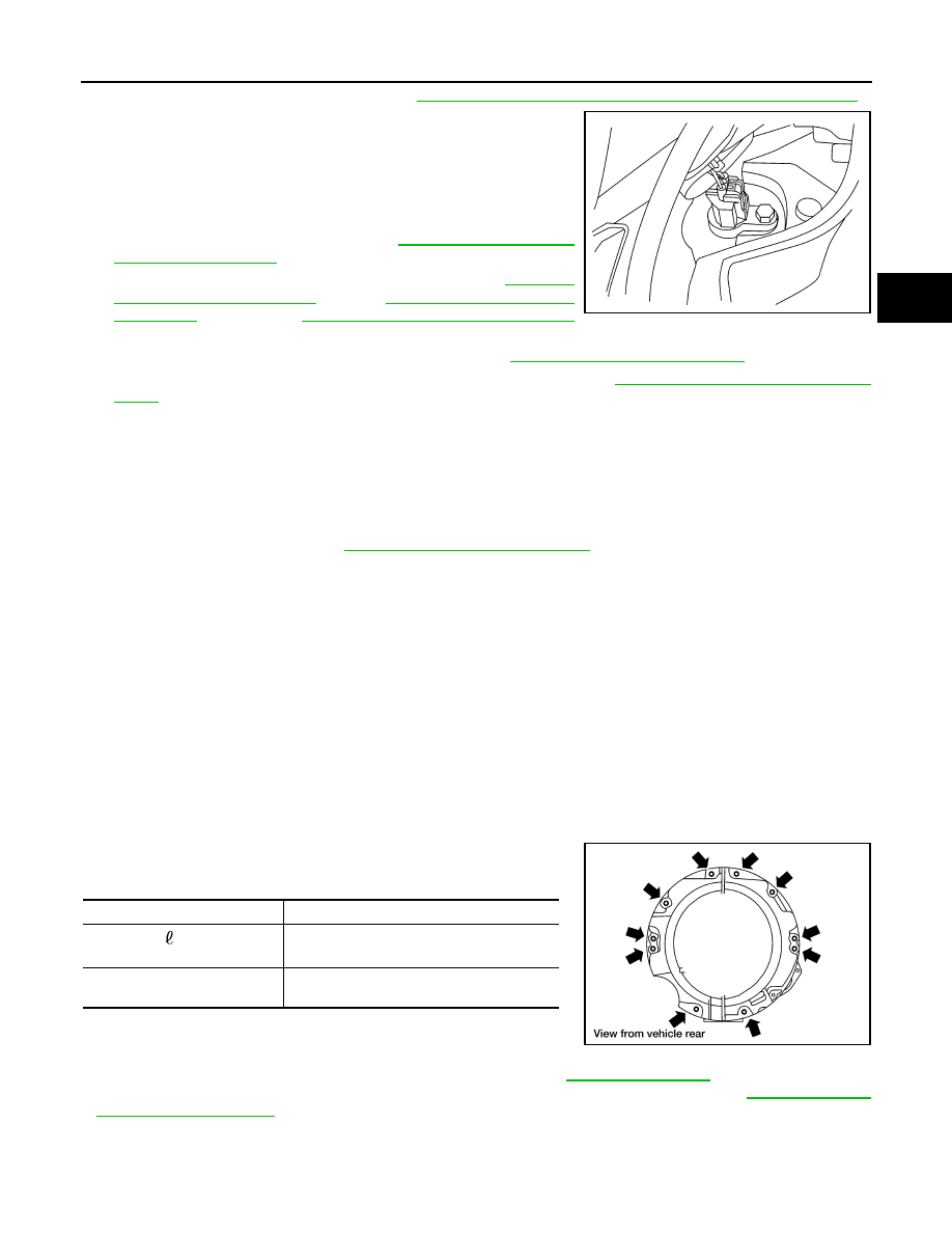
17. Remove the transmission to engine bolts using power tool.
18. Separate the transmission from the engine and remove it from the vehicle.
WARNING:
Support manual transmission while removing it.
INSTALLATION
Installation is in the reverse order of removal.
• When installing the transmission to the engine, tighten the bolts to
the specified torque.
CAUTION:
• When installing be careful to avoid interference between
transmission main drive gear and clutch cover.
• After installation, check for oil leakage and oil level. Refer to
.
• If flywheel is removed, align dowel pin with the smallest hole of flywheel. Refer to
.
• When replacing an engine or transmission you must make sure the dowels are installed correctly
during re-assembly.
LCIA0367E
Quantity
10
Bolt length “ ”
mm (in)
65 (2.56)
Tightening torque
N·m (kg-m, ft-lb)
75 (7.7, 55)
WCIA0507E