Content .. 1213 1214 1215 1216 ..
Nissan Frontier. Manual - part 1215
AIR BREATHER HOSE
TM-71
< REMOVAL AND INSTALLATION >
[6MT: FS6R31A]
C
E
F
G
H
I
J
K
L
M
A
B
TM
N
O
P
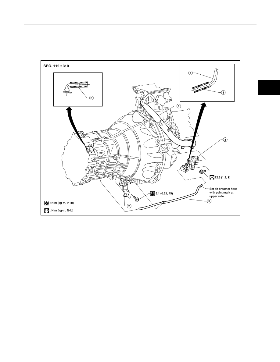
AIR BREATHER HOSE
Removal and Installation
INFOID:0000000009480447
COMPONENTS
REMOVAL
1. Disconnect air breather hose from breather tube and transmission harness connector.
2. Disconnect air breather hose from the bracket.
3. Remove the bracket bolt and remove the bracket from the transmission housing, if necessary.
4. Remove the breather tube bolt and the breather tube.
INSTALLATION
Installation is in the reverse order of removal.
CAUTION:
• Make sure there are no pinched or blocked areas on the air breather hose after installation.
• When inserting the air breather hose, be sure to insert it fully until its end reaches the end of the tube
radius.
• Install the air breather hose with the paint mark side up.
1.
Water outlet
2.
Bracket
3.
Air breather hose
4.
Breather tube
LCIA0392E