Nissan Frontier. Manual - part 1201


  Index      Nissan     Nissan Frontier (2014 year) - Service and Repair Manual


Search            


Content   ..  1199  1200  1201  1202   ..


Nissan Frontier. Manual - part 1201


REAR OIL SEAL

TM-15

< REMOVAL AND INSTALLATION >

[FS5R30A]

C

E

F

G

H

I

J

K

L

M

A

B

TM

N

O

P

REMOVAL AND INSTALLATION

REAR OIL SEAL

Removal and Installation

INFOID:0000000009480414
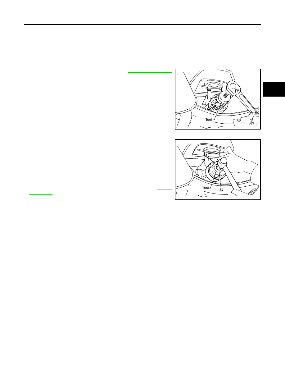
REMOVAL

1. Remove the rear propeller shaft. Refer to 

DLN-143, "Removal

and Installation"

.

2. Remove the rear oil seal using Tool.

CAUTION:

Do not reuse rear oil seal.

INSTALLATION

Installation is the reverse order of removal.

• Drive the new oil seal straight until it stops using Tool.

CAUTION:

• Do not reuse rear oil seal.

• Apply multi-purpose grease to oil seal lips before installing.

• Do not incline rear oil seal during installation.

• Check the transmission oil level after installation. Refer to 

TM-14,

"Checking"

.

Tool number

: ST33290001 (J-34286)

WCIA0176E

Tool number

: ST30720000 (J-25405)

WCIA0493E

TM-16

< REMOVAL AND INSTALLATION >

[FS5R30A]

POSITION SWITCH

POSITION SWITCH

Checking

INFOID:0000000009480415

BACK-UP LAMP SWITCH

• Check continuity.

PARK/NEUTRAL POSITION SWITCH

• Check continuity.

Gear position

Continuity

Reverse

Yes

Except reverse

No

SMT981D

Gear position

Continuity

Neutral

Yes

Except neutral

No

SHIFT CONTROL

TM-17

< REMOVAL AND INSTALLATION >

[FS5R30A]

C

E

F

G

H

I

J

K

L

M

A

B

TM

N

O

P

SHIFT CONTROL

Removal and Installation

INFOID:0000000009480416

COMPONENTS

REMOVAL

1. Remove the shift selector handle.
2. Remove the cup holder finisher and shift bezel. Refer to 

IP-29, "Exploded View"

.

3. Remove the retaining plate and dust boot covers.
4. Remove the clip B and then separate the boot from the control housing. 
5. Remove the snap ring. 
6. Remove the shift selector assembly from the transmission.

INSTALLATION

Installation is the reverse order of removal.

CAUTION:

• Do not reuse the clips and snap ring.

1.

Retaining plate

2.

Dust boot cover (upper)

3.

Dust boot cover (lower)

4.

Shift selector handle

5.

Shift selector assembly

6.

Clip A

7.

Boot

8.

Clip B

9.

Snap ring

AWDIA0626ZZ

TM-18

< REMOVAL AND INSTALLATION >

[FS5R30A]

SHIFT CONTROL

• Apply cement to threads of the shift selector assembly.

• When shift selector assembly is moved to each position, make sure there is no binding or discon-

nection in either boot.


Content   ..  1199  1200  1201  1202   ..