Nissan Frontier. Manual - part 1197


  Index      Nissan     Nissan Frontier (2014 year) - Service and Repair Manual


Search            


Content   ..  1195  1196  1197  1198   ..


Nissan Frontier. Manual - part 1197


STR-36

< REMOVAL AND INSTALLATION >

STARTER MOTOR

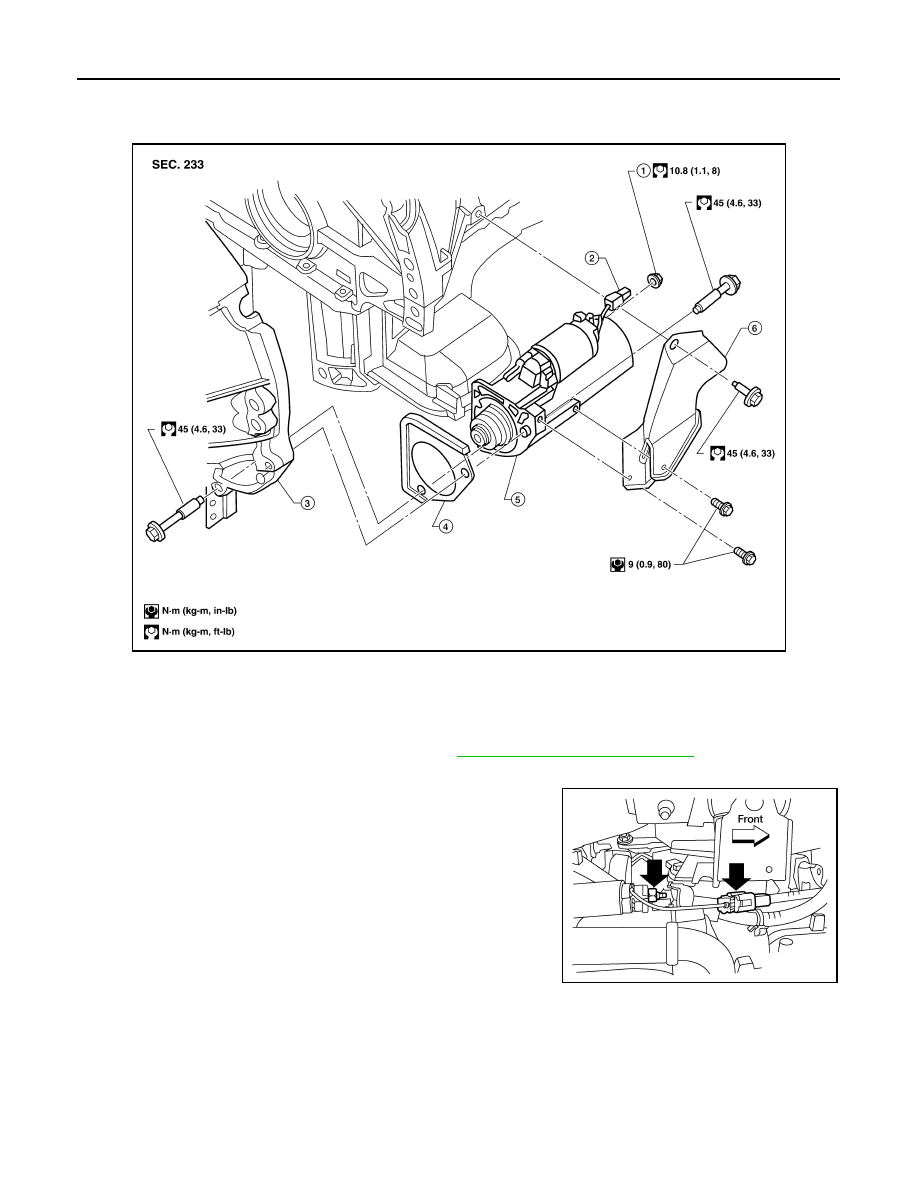
Removal and Installation (VQ40DE)

INFOID:0000000009482305

REMOVAL

1. Disconnect the negative battery terminal. Refer to 

PG-83, "Removal and Installation"

.

2. Remove starter cover bolts and starter cover.
3. Disconnect terminal "1" (S) connector and remove terminal "2"

(B) nut.

4. Remove the two starter motor bolts, using power tools.
5. Remove the starter motor.

INSTALLATION

Installation is in the reverse order of removal.

CAUTION:

Be sure to tighten terminal "2" nut carefully.

WKIA3792E

1.

Terminal "2"  (B) nut

2.

Terminal "1"  (S) connector

3.

Transmission housing

4.

Starter cover plate (rear)

5.

Starter motor assembly

6.

Starter cover

WKIA3189E

STARTER MOTOR

STR-37

< SERVICE DATA AND SPECIFICATIONS (SDS) 

C

D

E

F

G

H

I

J

K

L

M

A

STR

N

P

O

SERVICE DATA AND SPECIFICATIONS (SDS)

STARTER MOTOR

Starter

INFOID:0000000009482306

*: Always check with the Parts Department for the latest parts information.

Application

QR25DE

VQ40DE

Type*

Mitsubishi

M000T88281

Mitsubishi

M001TA0072

Reduction gear type

System voltage

12V

No-load

Terminal voltage

11V

Current

Less than 90A

Less than 120A

Revolution

More than 2,800 rpm

More than 3,100 rpm

TM-1

TRANSMISSION & DRIVELINE

C

E

F

G

H

I

J

K

L

M

SECTION 

TM

A

B

TM

N

O

P

CONTENTS

TRANSAXLE & TRANSMISSION

FS5R30A

PRECAUTION ...............................................

7

PRECAUTIONS ...................................................

7

Precaution for Supplemental Restraint System 
(SRS) "AIR BAG" and "SEAT BELT PRE-TEN-
SIONER" .................................................................
..

7

Precaution for Work  ..................................................

7

Service Notice or Precaution .....................................

7

PREPARATION ............................................

9

PREPARATION ...................................................

9

Special Service Tool  .................................................

9

Commercial Service Tool  ........................................

11

SYMPTOM DIAGNOSIS  ..............................

12

NOISE, VIBRATION AND HARSHNESS 
(NVH) TROUBLESHOOTING  ............................

12

NVH Troubleshooting Chart  ....................................

12

DESCRIPTION ...................................................

13

Description ..............................................................

13

PERIODIC MAINTENANCE .........................

14

M/T OIL ...............................................................

14

Changing .................................................................

14

Checking .................................................................

14

REMOVAL AND INSTALLATION ...............

15

REAR OIL SEAL  ................................................

15

Removal and Installation .........................................

15

POSITION SWITCH ............................................

16

Checking .................................................................

16

SHIFT CONTROL ...............................................

17

Removal and Installation .........................................

17

AIR BREATHER HOSE  ....................................

19

Removal and Installation  .........................................

19

UNIT REMOVAL AND INSTALLATION ......

21

TRANSMISSION ASSEMBLY  ..........................

21

Removal and Installation from Vehicle  ....................

21

UNIT DISASSEMBLY AND ASSEMBLY  ....

23

TRANSMISSION ASSEMBLY  ..........................

23

Overhaul ..................................................................

23

CASE COMPONENTS  ......................................

30

Disassembly ............................................................

30

Assembly .................................................................

32

SHIFT CONTROL COMPONENTS ...................

35

Disassembly ............................................................

35

Inspection ................................................................

35

Assembly .................................................................

36

GEAR COMPONENTS ......................................

37

Disassembly ............................................................

37

Inspection ................................................................

41

Assembly .................................................................

43

SERVICE DATA AND SPECIFICATIONS 
(SDS) ............................................................

53

SERVICE DATA AND SPECIFICATIONS 
(SDS) .................................................................

53

General Specification  ..............................................

53

Gear End Play  .........................................................

54

Baulk Ring Clearance ..............................................

54

Available Snap Rings  ..............................................

54

Available C-Rings  ....................................................

55

Available Thrust Washer  .........................................

55

Available Shims  .......................................................

55

6MT: FS6R31A

PRECAUTION ..............................................

56

TM-2

PRECAUTIONS  .................................................

56

Precaution for Supplemental Restraint System 
(SRS) "AIR BAG" and "SEAT BELT PRE-TEN-
SIONER" ................................................................
.

56

Precaution for Work ................................................

56

Service Notice or Precaution  ..................................

56

PREPARATION ...........................................

58

PREPARATION  .................................................

58

Special Service Tool ...............................................

58

Commercial Service Tool  .......................................

60

SYMPTOM DIAGNOSIS  .............................

62

NOISE, VIBRATION AND HARSHNESS 
(NVH) TROUBLESHOOTING ............................

62

NVH Troubleshooting Chart  ...................................

62

DESCRIPTION ...................................................

63

Cross-Sectional View  .............................................

63

PERIODIC MAINTENANCE ........................

65

M/T OIL  ..............................................................

65

Changing ................................................................

65

Checking .................................................................

65

REMOVAL AND INSTALLATION ...............

66

REAR OIL SEAL ................................................

66

Removal and Installation  ........................................

66

POSITION SWITCH  ...........................................

68

Checking .................................................................

68

SHIFT CONTROL  ..............................................

69

Removal and Installation  ........................................

69

AIR BREATHER HOSE  .....................................

71

Removal and Installation  ........................................

71

UNIT REMOVAL AND INSTALLATION  .....

72

TRANSMISSION ASSEMBLY ...........................

72

Removal and Installation from Vehicle (For 2WD 
Models) ..................................................................
.

72

Removal and Installation from Vehicle (For 4WD 
Models) ..................................................................
.

74

UNIT DISASSEMBLY AND ASSEMBLY ....

77

TRANSMISSION ASSEMBLY ...........................

77

Overhaul .................................................................

77

CASE COMPONENTS .......................................

83

Disassembly ...........................................................

83

Assembly ................................................................

87

SHIFT CONTROL COMPONENTS  ...................

94

Disassembly ...........................................................

94

Inspection ...............................................................

97

Assembly ................................................................

97

GEAR COMPONENTS  .....................................

102

Disassembly ..........................................................

102

Inspection ..............................................................

108

Assembly ..............................................................

111

SERVICE DATA AND SPECIFICATIONS 
(SDS) .........................................................

125

SERVICE DATA AND SPECIFICATIONS 
(SDS) ................................................................

125

General Specification ............................................

125

Gear End Play .......................................................

126

Snap Rings  ...........................................................

126

Baulk Ring Clearance  ...........................................

126

5AT: RE5R05A

BASIC INSPECTION .................................

128

DIAGNOSIS AND REPAIR WORKFLOW ........

128

How to Perform Trouble Diagnosis for Quick and 
Accurate Repair  ....................................................

128

Diagnostic Work Sheet  .........................................

129

INSPECTION AND ADJUSTMENT ..................

131

ADDITIONAL SERVICE WHEN REPLACING 
TRANSMISSION ASSEMBLY  ................................

131

ADDITIONAL SERVICE WHEN REPLACING 
TRANSMISSION ASSEMBLY : Description  .........

131

ADDITIONAL SERVICE WHEN REPLACING 
TRANSMISSION ASSEMBLY : Special Repair 
Requirement .........................................................

131

SYSTEM DESCRIPTION  ..........................

132

A/T CONTROL SYSTEM ..................................

132

Cross-Sectional View ............................................

132

Shift Mechanism  ...................................................

133

TCM Function  .......................................................

144

CAN Communication  ............................................

145

Input/Output Signal of TCM  ..................................

146

Line Pressure Control  ...........................................

146

Shift Control  ..........................................................

148

Lock-up Control .....................................................

149

Engine Brake Control ............................................

150

Control Valve  ........................................................

150

A/T Electrical Parts Location .................................

152

A/T SHIFT LOCK SYSTEM ..............................

154

System Description  ...............................................

154

Component Parts Location  ...................................

154

ON BOARD DIAGNOSTIC (OBD) SYSTEM ....

155

Introduction ...........................................................

155

OBD-II Function for A/T System  ...........................

155

One or Two Trip Detection Logic of OBD-II  ..........

155

OBD-II Diagnostic Trouble Code (DTC) ................

155

Malfunction Indicator Lamp (MIL)  .........................

156

DIAGNOSIS SYSTEM (TCM)  ...........................

157

CONSULT Function (TRANSMISSION)  ...............

157


Content   ..  1195  1196  1197  1198   ..