Content .. 1094 1095 1096 1097 ..
Nissan Frontier. Manual - part 1096
RF-10
< DTC/CIRCUIT DIAGNOSIS >
POWER SUPPLY AND GROUND CIRCUIT
DTC/CIRCUIT DIAGNOSIS
POWER SUPPLY AND GROUND CIRCUIT
SUNROOF MOTOR ASSEMBLY
SUNROOF MOTOR ASSEMBLY : Diagnosis Procedure
INFOID:0000000009482344
Regarding Wiring Diagram information, refer to
SUNROOF MOTOR ASSEMBLY
1.
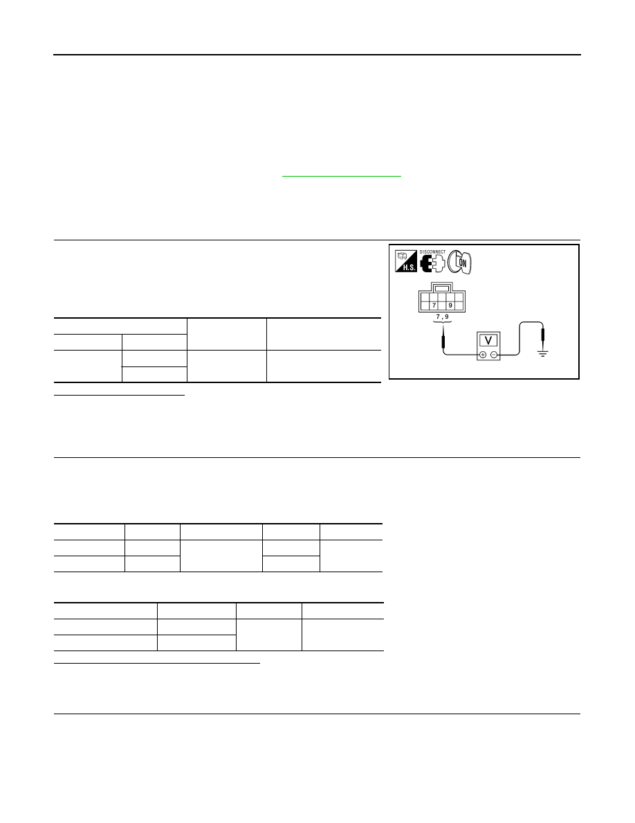
CHECK SUNROOF MOTOR POWER SUPPLY
1. Turn ignition switch OFF.
2. Disconnect sunroof motor assembly connector B83.
3. Turn ignition switch ON.
4. Check voltage between sunroof motor assembly connector B83
terminals 7 and 9 and ground.
Is the voltage as specified?
YES
>> GO TO 7
NO (With power seats) >>GO TO 2
NO (Without power seats) >>GO TO 5
2.
CHECK SUNROOF MOTOR POWER SUPPLY CIRCUITS
1. Turn ignition switch OFF.
2. Disconnect BCM connector M20 and circuit breaker-2 connector M82.
3. Check continuity between BCM connector M20, circuit breaker-2 connector M82 and sunroof motor
assembly connector B83.
4. Check continuity between BCM connector M20, circuit breaker-2 and ground.
Are the continuity test results as specified?
YES
>> GO TO 3
NO
>> Repair or replace harness.
3.
CHECK BCM OUTPUT SIGNAL
1. Connect BCM connector M20.
2. Turn ignition switch ON.
3. Check voltage between BCM connector M20 and ground.
(+)
(–)
Voltage
Connector
Terminal
B83
7
Ground
Battery voltage
9
ALKIA1176GB
Connector
Terminal
Connector
Terminal
Continuity
M20
68
B83
9
Yes
M82
1 7
Connector
Terminal
—
Continuity
M20
68
Ground
No
M82
1