Content .. 1085 1086 1087 1088 ..
Nissan Frontier. Manual - part 1087
PWO-6
< PREPARATION >
PREPARATION
PREPARATION
PREPARATION
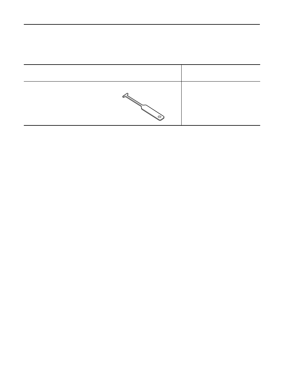
Special Service Tool
INFOID:0000000009480403
The actual shape of the tools may differ from those illustrated here.
Tool number
(TechMate No.)
Tool name
Description
—
(J-42059)
Power socket removal tool
Removing power sockets
AWMIA1148GB