Nissan Frontier. Manual - part 1042


  Index      Nissan     Nissan Frontier (2014 year) - Service and Repair Manual


Search            


Content   ..  1040  1041  1042  1043   ..


Nissan Frontier. Manual - part 1042


PCS-12

< SYSTEM DESCRIPTION >

[IPDM E/R]

DIAGNOSIS SYSTEM (IPDM E/R)
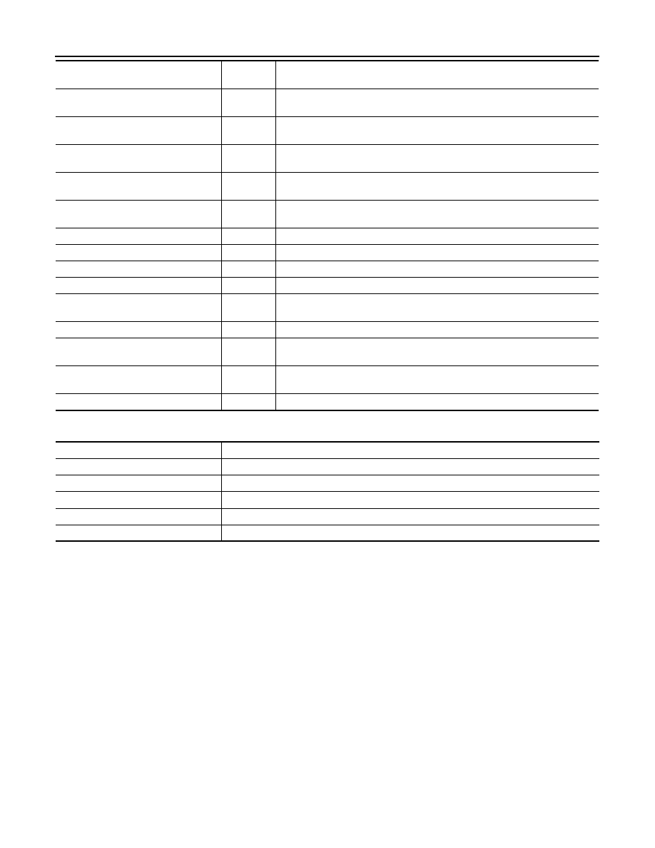
ACTIVE TEST

TAIL&CLR REQ [On/Off]

×

Indicates position light request signal received from BCM on CAN communica-
tion line

HL LO REQ [On/Off]

×

Indicates low beam request signal received from BCM on CAN communication 
line

HL HI REQ [On/Off]

×

Indicates high beam request signal received from BCM on CAN communication 
line

FR FOG REQ [On/Off]

×

Indicates front fog light request signal received from BCM on CAN communica-
tion line

FR WIP REQ [Stop/1LOW/Low/Hi]

×

Indicates front wiper request signal received from BCM on CAN communication 
line

WIP AUTO STOP [STOP P/ACT P]

×

Indicates condition of front wiper auto stop signal

WIP PROT [Off/BLOCK]

×

Indicates condition of front wiper fail-safe operation

ST RLY REQ [On/Off]

Indicates starter request signal received from ECM on CAN communication line

IGN RLY [On/Off]

×

Indicates condition of ignition relay

RR DEF REQ [On/Off]

×

Indicates rear defogger request signal received from BCM on CAN communica-
tion line

OIL P SW [Open/Close]

Indicates condition of oil pressure switch

DTRL REQ [Off]

Indicates daytime light request signal received from BCM on CAN communica-
tion line

THFT HRN REQ [On/Off]

Indicates theft warning horn request signal received from BCM on CAN commu-
nication line

HORN CHIRP [On/Off]

Indicates horn reminder signal received from BCM on CAN communication line

Monitor Item [Unit]

Main

Signals

Description

Test item

Description

REAR DEFOGGER

This test is able to check rear defogger operation [On/Off].

FRONT WIPER

This test is able to check wiper motor operation [Hi/Lo/Off].

MOTOR FAN

This test is able to check cooling fan operation [4/3/2/1].

EXTERNAL LAMPS

This test is able to check external lamp operation [Fog/Hi/Lo/TAIL/Off].

HORN

This test is able to check horn operation [On].

PCS

U1000 CAN COMM CIRCUIT

PCS-13

< DTC/CIRCUIT DIAGNOSIS >

[IPDM E/R]

C

D

E

F

G

H

I

J

K

L

B

A

O

P

N

DTC/CIRCUIT DIAGNOSIS

U1000 CAN COMM CIRCUIT

Description

INFOID:0000000009478247

Refer to 

LAN-4, "System Description"

.

DTC Logic

INFOID:0000000009478248

DTC DETECTION LOGIC

DTC CONFIRMATION PROCEDURE

Diagnosis Procedure

INFOID:0000000009478249

1.

 PERFORM SELF DIAGNOSTIC

1. Turn ignition switch ON and wait for 2 seconds or more.

2. Check “SELF-DIAG RESULTS” of IPDM E/R.
Is “CAN COMM CIRCUIT” displayed?

YES

>> Refer to 

LAN-14, "Trouble Diagnosis Flow Chart"

.

NO

>> Refer to 

GI-42, "Intermittent Incident"

.

DTC

CONSULT display de-

scription

DTC Detection Condition

Possible cause

U1000

CAN COMM CIRCUIT

When IPDM E/R cannot communicate CAN 
communication signal continuously for 2 
seconds or more

In CAN communication system, any item (or items) 
of the following listed below is malfunctioning.
• Receiving (TCM)
• Receiving (ECM)
• Receiving (BCM)
• Receiving (Combination meter)

PCS-14

< DTC/CIRCUIT DIAGNOSIS >

[IPDM E/R]

POWER SUPPLY AND GROUND CIRCUIT

POWER SUPPLY AND GROUND CIRCUIT

Diagnosis Procedure

INFOID:0000000009478250

Regarding Wiring Diagram information, refer to 

PCS-22, "Wiring Diagram"

.

1.

 CHECK FUSIBLE LINKS

Check that the following IPDM E/R fusible links are not blown.

Is the fusible link blown?

YES

>> Replace the blown fusible link after repairing the affected circuit.

NO

>> GO TO 2

2.

 CHECK BATTERY POWER SUPPLY CIRCUIT

1. Turn ignition switch OFF.

2. Disconnect IPDM E/R.

3. Check voltage between IPDM E/R harness connectors and

ground.

Is there voltage on all pins?

YES

>> GO TO 3

NO

>> Repair or replace harness.

3.

 CHECK GROUND CIRCUIT

1. Turn ignition switch OFF.

2. Check continuity between IPDM E/R harness connectors and

ground.

Does continuity exist?

YES

>> Inspection End.

NO

>> Repair or replace harness.

Terminal No.

Signal name

Fusible link No.

1

Battery

A, D

2

C

22

A, E, I

Terminals

Ignition 

switch posi-

tion

Voltage (V)

(Approx.)

(+)

(

−)

Connector

Terminal

E118 (A)

1

Ground

OFF

Battery
voltage

2

E120 (B)

22

AWMIA0506ZZ

IPDM E/R

Ground

Continuity

Connector

Terminal

E122 (A)

38

Yes

E124 (B)

59

AWMIA0024ZZ

PCS

IPDM E/R (INTELLIGENT POWER DISTRIBUTION MODULE ENGINE ROOM)

PCS-15

< ECU DIAGNOSIS INFORMATION >

[IPDM E/R]

C

D

E

F

G

H

I

J

K

L

B

A

O

P

N

ECU DIAGNOSIS INFORMATION

IPDM E/R (INTELLIGENT POWER DISTRIBUTION MODULE ENGINE
ROOM)

Reference Value

INFOID:0000000009478251

VALUES ON THE DIAGNOSIS TOOL

Monitor Item

Condition

Value/Status

MOTOR FAN REQ

Engine idle speed

Changes depending on engine 
coolant temperature, air conditioner 
operation status, vehicle speed, 
etc.

 1, 2, 3, 4

A/C COMP REQ

A/C switch OFF

Off

A/C switch ON

On

TAIL&CLR REQ

Lighting switch OFF

Off

Lighting switch 1ST, 2ND, HI or AUTO (Light is illuminated)

On

HL LO REQ

Lighting switch OFF

Off

Lighting switch 2ND HI or AUTO (Light is illuminated)

On

HL HI REQ

Lighting switch OFF

Off

Lighting switch HI

On

FR FOG REQ

Lighting switch 2ND

Front fog lamp switch OFF

Off

Front fog lamp switch ON

On

FR WIP REQ

Ignition switch ON

Front wiper switch OFF

Stop

Front wiper switch INT

1LOW

Front wiper switch LO

Low

Front wiper switch HI

HI

WIP AUTO STOP

Ignition switch ON

Front wiper stop position

STOP P

Any position other than front wiper 
stop position

ACT P

WIP PROT

Ignition switch ON

Front wiper operates normally

Off

Front wiper stops at fail-safe opera-
tion

BLOCK

ST RLY REQ

Ignition switch OFF or ACC

Off

Ignition switch START

On

IGN RLY

Ignition switch OFF or ACC

Off

Ignition switch ON

On

RR DEF REQ

Rear defogger switch OFF

Off

Rear defogger switch ON

On

OIL P SW

Ignition switch OFF, ACC or engine running

Open

Ignition switch ON

Close

DTRL REQ

Daytime light system requested OFF with CONSULT.

Off

Daytime light system requested ON with CONSULT.

On

THFT HRN REQ

Not operated

Off

• Panic alarm is activated
• Horn is activated with VEHICLE SECURITY (THEFT WARNING) SYS-

TEM

On


Content   ..  1040  1041  1042  1043   ..