Nissan Frontier. Manual - part 1040


  Index      Nissan     Nissan Frontier (2014 year) - Service and Repair Manual


Search            


Content   ..  1038  1039  1040  1041   ..


Nissan Frontier. Manual - part 1040


PCS-4

< SYSTEM DESCRIPTION >

[IPDM E/R]

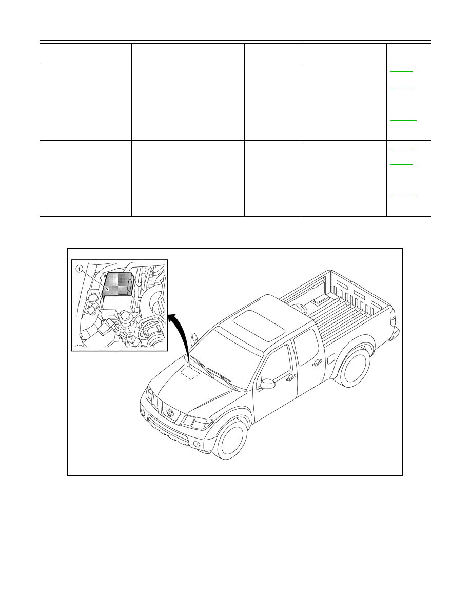
RELAY CONTROL SYSTEM

Component Parts Location

INFOID:0000000009478237

Fuel pump relay

Fuel pump request signal

ECM (CAN)

Fuel pump

EC-442


(QR25DE)

EC-932


(VQ40DE for 
USA and 
Canada)

EC-1350


(VQ40DE for 
Mexico)

Ignition relay

Ignition switch ON signal

Ignition switch

Ignition relay

EC-446


(QR25DE)

EC-935


(VQ40DE for 
USA and 
Canada)

EC-1354


(VQ40DE for 
Mexico)

Control relay

Input/output

Transmit unit

Control part

Reference 

page

1.

IPDM E/R E118, E119, E120, E121, 
E122, E123, E124

AWMIA0532ZZ

PCS

POWER CONTROL SYSTEM

PCS-5

< SYSTEM DESCRIPTION >

[IPDM E/R]

C

D

E

F

G

H

I

J

K

L

B

A

O

P

N

POWER CONTROL SYSTEM

System Diagram

INFOID:0000000009478238

System Description

INFOID:0000000009478239

COOLING FAN CONTROL

IPDM E/R controls the cooling fan according to the status of the cooling fan speed request signal received

from ECM via CAN communication. Refer to 

LAN-4, "System Description"

.

AWMIA0527GB

PCS-6

< SYSTEM DESCRIPTION >

[IPDM E/R]

SIGNAL BUFFER SYSTEM

SIGNAL BUFFER SYSTEM

System Diagram

INFOID:0000000009478240

System Description

INFOID:0000000009478241

IPDM E/R reads the status of the oil pressure switch and transmits the oil pressure switch signal to BCM via

CAN communication. Refer to 

LAN-4, "System Description"

.

AWMIA1129GB

PCS

POWER CONSUMPTION CONTROL SYSTEM

PCS-7

< SYSTEM DESCRIPTION >

[IPDM E/R]

C

D

E

F

G

H

I

J

K

L

B

A

O

P

N

POWER CONSUMPTION CONTROL SYSTEM

System Diagram

INFOID:0000000009478242

System Description

INFOID:0000000009478243

OUTLINE

• IPDM E/R incorporates a power consumption control function that reduces the power consumption accord-

ing to the vehicle status. 

• IPDM E/R changes its status (control mode) with the sleep wake up signal received from BCM via CAN com-

munication.

Normal mode (wake-up)

- CAN communication is normally performed with other control units.

- Individual unit control by IPDM E/R is normally performed.

Low power consumption mode (sleep)

- Low power consumption control is active.

- CAN transmission is stopped.

SLEEP MODE ACTIVATION

• IPDM E/R judges that the sleep-ready conditions are fulfilled when the ignition switch is OFF and none of the

conditions below are present. Then it transmits a sleep-ready signal (ready) to BCM via CAN communica-

tion.

- Front wiper fail-safe operation 

- Outputting signals to actuators

- Switches or relays operating

- Auto active test is starting

- Emergency OFF

- Output requests are being received from control units via CAN communication.

• IPDM E/R stops CAN communication and enters the low power consumption mode when it receives a sleep

wake up signal (sleep) from BCM and the sleep-ready conditions are fulfilled.

WAKE-UP OPERATION

• IPDM E/R changes from the low power consumption mode to the normal mode when it receives a sleep

wake-up signal (wake up) from BCM or any of the following conditions is fulfilled. In addition, it transmits a

sleep-ready signal (not-ready) to BCM via CAN communication to report the CAN communication start.

- Ignition switch ON

- An output request is received from a control unit via CAN communication.

ALCIA0030GB


Content   ..  1038  1039  1040  1041   ..