Nissan Frontier. Manual - part 1001


  Index      Nissan     Nissan Frontier (2014 year) - Service and Repair Manual


Search            


Content   ..  999  1000  1001  1002   ..


Nissan Frontier. Manual - part 1001


ENGINE MAINTENANCE (VQ40DE)

MA-31

< PERIODIC MAINTENANCE >

C

D

E

F

G

H

I

J

K

L

M

B

MA

N

O

A

ENGINE MAINTENANCE (VQ40DE)

DRIVE BELT
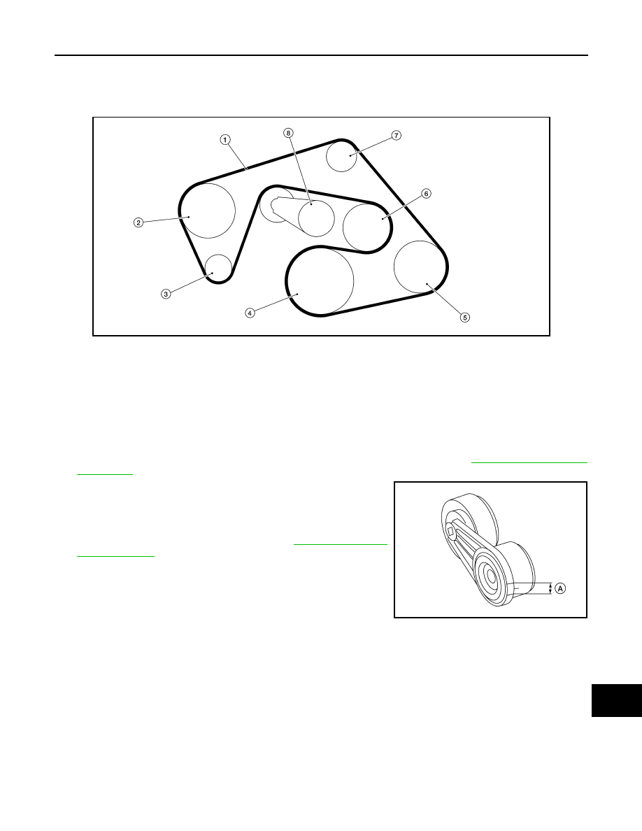
DRIVE BELT : Exploded View

INFOID:0000000009478636

DRIVE BELT : Checking Drive Belts

INFOID:0000000009478637

WARNING:

Be sure to perform when the engine is stopped.
1. Remove air duct and resonator assembly when inspecting drive belt. Refer to 

EM-141, "Removal and

Installation"

.

2. Make sure that the drive belt tensioner indicator is within the

allowable working range (A) as shown.

3. Visually check entire belt for wear, damage or cracks.
4. If the indicator is out of allowable working range or drive belt is

damaged, replace the drive belt. Refer to 

EM-129, "Removal

and Installation"

.

DRIVE BELT : Adjustment

INFOID:0000000009478638

There is no manual drive belt tension adjustment. The drive belt tension is automatically adjusted by the drive

belt auto-tensioner.

ENGINE COOLANT
ENGINE COOLANT : System Inspection

INFOID:0000000009478639

WARNING:

• Do not remove the radiator/reservoir cap when the engine is hot. Serious burns could occur from

high pressure fluid escaping from the radiator or reservoir.

• Wrap a thick cloth around the cap. Slowly push down and turn it a quarter turn to allow built-up pres-

sure to escape. Carefully remove the cap by pushing down and turning it all the way.

LBIA0427E

1.

Drive belt

2.

Power steering oil pump pulley

3.

Generator pulley

4.

Crankshaft pulley

5.

A/C compressor

6.

Cooling fan pulley

7.

Idler pulley

8.

Drive belt tensioner

AWBIA0723ZZ

MA-32

< PERIODIC MAINTENANCE >

ENGINE MAINTENANCE (VQ40DE)

CHECKING COOLING SYSTEM HOSES

Check hoses for the following:

• Improper attachment

• Leaks

• Cracks

• Damage

• Loose connections

• Chafing

• Deterioration

CHECKING RESERVOIR LEVEL

• Check if the engine coolant reservoir tank level is within MIN to

MAX when the engine is cool.

• Adjust engine coolant level as necessary.

ENGINE COOLANT : Changing Engine Coolant

INFOID:0000000009478640

WARNING:

• To avoid being scalded, do not change the coolant when the engine is hot.

• Wrap a thick cloth around the cap to carefully remove the cap. First, turn the cap a quarter of a turn

to release any built-up pressure, then push down and turn the cap all the way to remove it.

• Avoid direct skin contact with used coolant. If skin contact is made, wash thoroughly with soap or

hand cleaner as soon as possible.When removing components such as hoses, tubes/lines, etc., cap

or plug openings to prevent fluid from spilling.

• Keep coolant out of the reach of children and pets.

DRAINING ENGINE COOLANT

1. Turn ignition switch ON and set temperature control lever all the way to HOT position or the highest tem-

perature position. Wait 10 seconds and turn ignition switch OFF.

2. Remove the engine under cover. Refer to 

EXT-15, "Removal and Installation"

.

3. Open the radiator drain plug at the bottom of the radiator, and

remove the reservoir cap. This is the only step required when

partially draining the cooling system (radiator only). 

CAUTION:

• Do not allow the coolant to contact the drive belts. 

• Perform this step when engine is cold.

SMA412B

LLIA0070E

ENGINE MAINTENANCE (VQ40DE)

MA-33

< PERIODIC MAINTENANCE >

C

D

E

F

G

H

I

J

K

L

M

B

MA

N

O

A

4. When draining all of the coolant in the system for engine

removal or repair, it is necessary to drain the cylinder block.

Remove the cylinder block drain plugs (A), (B), (C), (D) and

block heater (if equipped), to drain the cylinder block as shown.

CAUTION:

Do not reuse copper sealing washers.

NOTE:

For Canada, the (D) cylinder block drain plug as shown, is not a

cylinder block drain plug but a block heater.

5. Remove the reservoir tank to drain the engine coolant, then clean the reservoir tank before installing it.
6. Check the drained coolant for contaminants such as rust, corrosion or discoloration.

If the coolant is contaminated, flush the engine cooling system. Follow the "Flushing Cooling System" pro-

cedure.

REFILLING ENGINE COOLANT

1. Close the radiator drain plug. Install the reservoir tank, cylinder

block drain plugs (A), (B), (C), (D) and block heater (if

equipped), if removed for a total system drain or for engine

removal or repair.

• The radiator must be completely empty of coolant and water.

• Apply sealant to the threads of the cylinder block drain plugs

(A), (B), (C), (D). Use Genuine High Performance Thread

Sealant or equivalent. Refer to 

GI-21, "Recommended Chemi-

cal Products and Sealants"

.

• Tighten each plug to the specified torque. Refer to 

EM-220,

"Disassembly and Assembly"

.

2. Set the vehicle heater controls to the full HOT and heater ON position. Turn the vehicle ignition ON with

the engine OFF as necessary to activate the heater mode.

3. Remove the vented reservoir cap and replace it with a non-vented reservoir cap before filling the cooling

system.

WLIA0020E

WLIA0020E

MA-34

< PERIODIC MAINTENANCE >

ENGINE MAINTENANCE (VQ40DE)

4. Install the Tool by installing the radiator cap adapter onto the

radiator neck opening. Then attach the gauge body assembly

with the refill tube and the venturi assembly to the radiator cap

adapter.

5. Insert the refill hose into the coolant mixture container that is

placed at floor level. Make sure the ball valve is in the closed

position. 

CAUTION:

Do not use any cooling system additives such as radiator

sealer. Additives may clog the cooling system and cause

damage to the engine, transmission and/or cooling system.

NOTE:

Use recommended coolant or equivalent. Refer to 

MA-16, "FOR

USA AND CANADA : Fluids and Lubricants"

 (United States and

Canada) or 

MA-18, "FOR MEXICO : Fluids and Lubricants"

(Mexico).

6. Install an air hose to the venturi assembly, the air pressure must be within specification. 

CAUTION:

The compressed air supply must be equipped with an air dryer.

7. The vacuum gauge will begin to rise and there will be an audible hissing noise. During this process open

the ball valve on the refill hose slightly. Coolant will be visible rising in the refill hose. Once the refill hose is

full of coolant, close the ball valve. This will purge any air trapped in the refill hose.

8. Continue to draw the vacuum until the gauge reaches 28 inches

of vacuum. The gauge may not reach 28 inches in high altitude

locations, use the vacuum specifications based on the altitude

above sea level.

9. When the vacuum gauge has reached the specified amount, disconnect the air hose and wait 20 seconds

to see if the system loses any vacuum. If the vacuum level drops, perform any necessary repairs to the

system and repeat steps 6 - 8 to bring the vacuum to the specified amount. Recheck for any leaks. 

10. Place the coolant container (with the refill hose inserted) at the same level as the top of the radiator. Then

open the ball valve on the refill hose so the coolant will be drawn up to fill the cooling system. The cooling

system is full when the vacuum gauge reads zero.

CAUTION:

Do not allow the coolant container to get too low when filling, to avoid air from being drawn into

the cooling system. 

11. Remove the Tool from the radiator neck opening and install the radiator cap.
12. Remove the non-vented reservoir cap.
13. Fill the cooling system reservoir tank to the specified level. Run the engine to warm up the cooling system

and top up the system as necessary before installing the vented reservoir cap.

Tool number

: KV991J0070 (J-45695)

Cooling system capacity 
(with reservoir)

: Refer to 

MA-16

 (United 

States and Canada), 

MA-

18

 (Mexico).

Compressed air 
supply pressure

: 549 - 824 kPa (5.6 - 8.4 kg/cm

2

80 - 120 psi)

LLIA0058E

Altitude above sea level

Vacuum gauge reading

0 - 100 m (328 ft)

: 28 inches of vacuum

300 m (984 ft)

: 27 inches of vacuum

500 m (1,641 ft)

: 26 inches of vacuum

1,000 m (3,281 ft)

: 24 - 25 inches of vacuum

LLIA0057E


Content   ..  999  1000  1001  1002   ..