Nissan Sentra. Manual - part 924
WCS
THE SEAT BELT REMINDER WARNING CONTINUES SOUNDING, OR DOES
NOT SOUND
WCS-33
< SYMPTOM DIAGNOSIS >
C
D
E
F
G
H
I
J
K
L
M
B
A
O
P
THE SEAT BELT REMINDER WARNING CONTINUES SOUNDING, OR
DOES NOT SOUND
Description
INFOID:0000000009759254
• Seat belt reminder warning does not sound.
• Seat belt reminder warning sounds continuously.
Diagnosis Procedure
INFOID:0000000009759255
1.
CHECK SEAT BELT WARNING LAMP
1. Turn ignition switch ON.
2. Check the operation of the seat belt warning lamp in the combination meter.
Is the inspection result normal?
YES
>> Replace combination meter. Refer to
MWI-77, "Removal and Installation"
NO
>> GO TO 2.
2.
CHECK SEAT BELT BUCKLE SWITCH (LH) SIGNAL CIRCUIT
Check the seat belt buckle switch (LH) circuit. Refer to
Is the inspection result normal?
YES
>> GO TO 3.
NO
>> Repair or replace harness or connector.
3.
CHECK SEAT BELT BUCKLE SWITCH (LH)
Check the seat belt buckle switch (LH). Refer to
WCS-30, "Component Inspection"
.
Is the inspection result normal?
YES
>> Replace combination meter. Refer to
MWI-77, "Removal and Installation"
NO
>> Replace seat belt buckle (LH). Refer to
SR-32, "Removal and Installation"
.
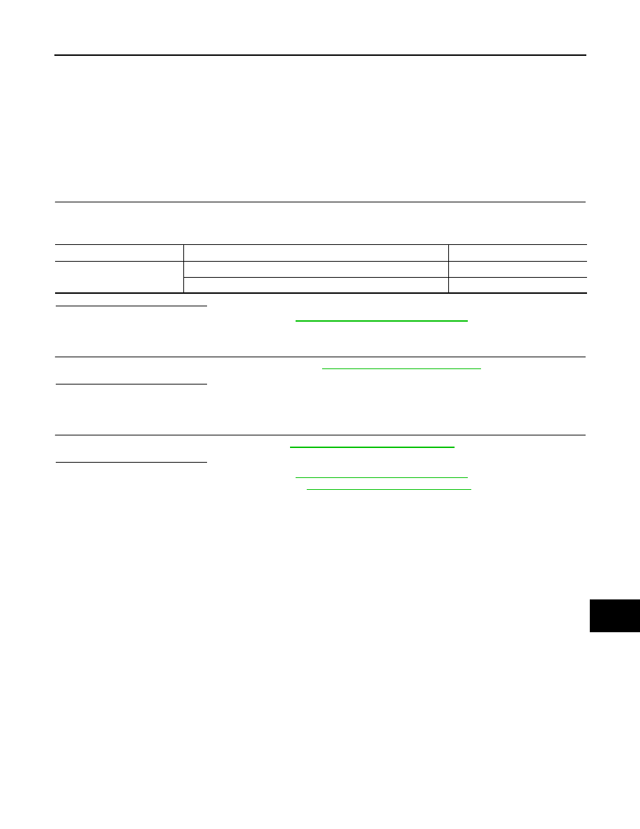
Combination meter
Condition
Status
Seat belt warning lamp
When seat belt LH (driver seat) is fastened
OFF
When seat belt LH (driver seat) is unfastened
ON