Nissan Sentra. Manual - part 922
WCS
POWER SUPPLY AND GROUND CIRCUIT
WCS-25
< DTC/CIRCUIT DIAGNOSIS >
C
D
E
F
G
H
I
J
K
L
M
B
A
O
P
DTC/CIRCUIT DIAGNOSIS
POWER SUPPLY AND GROUND CIRCUIT
COMBINATION METER
COMBINATION METER : Diagnosis Procedure
INFOID:0000000010289405
Regarding Wiring Diagram information, refer to
.
1.
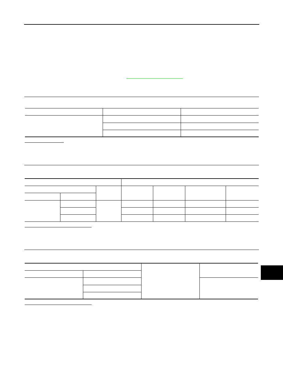
CHECK FUSES
Check that the following fuses are not blown.
Is the fuse blown?
YES
>> Replace the blown fuse after repairing the affected circuit.
NO
>> GO TO 2.
2.
POWER SUPPLY CIRCUIT CHECK
Check voltage between combination meter harness connector M24 terminals 15, 27, 28 and ground.
Is the inspection result normal?
YES
>> GO TO 3.
NO
>> Repair or replace harness or connector.
3.
CHECK GROUND CIRCUIT
Check continuity between combination meter harness connector M24 terminals 21, 22, 23 and ground.
Is the inspection result normal?
YES
>> Inspection End.
NO
>> Repair or replace harness or connector.
BCM (BODY CONTROL SYSTEM) (WITH INTELLIGENT KEY SYSTEM)
BCM (BODY CONTROL SYSTEM) (WITH INTELLIGENT KEY SYSTEM) : Diagnosis
Procedure
INFOID:0000000010309901
Unit
Power source
Fuse No.
Combination meter
Battery 8
Ignition switch ON or ACC
18
Ignition switch ON or START
3
Terminals
Ignition switch position
(+)
(–)
OFF
ACC
ON
START
Connector
Terminal
M24
27
Ground
Battery voltage
Battery voltage
Battery voltage
Battery voltage
15
0V
Battery voltage
Battery voltage
0V
28
0V
0V
Battery voltage
Battery voltage
Combination meter
Ground
Continuity
Connector
Terminal
M24
21
Yes
22
23