Nissan Sentra. Manual - part 895
TM-216
< DTC/CIRCUIT DIAGNOSIS >
[CVT: RE0F11A]
P099C SHIFT SOLENOID G
P099C SHIFT SOLENOID G
DTC Logic
INFOID:0000000009759465
DTC DETECTION LOGIC
DTC CONFIRMATION PROCEDURE
1.
PREPARATION BEFORE WORK
If another “DTC CONFIRMATION PROCEDURE” occurs just before, turn ignition switch OFF and wait for at
least 10 seconds, then perform the next test.
>> GO TO 2.
2.
CHECK DTC DETECTION
1. Start the engine and wait for 5 seconds or more
2. Check the first trip DTC.
Is “P099C” detected?
YES
>> Go to
NO
>> INSPECTION END
Diagnosis Procedure
INFOID:0000000009759466
1.
CHECK CIRCUIT BETWEEN TCM AND CVT UNIT
1. Turn ignition switch OFF.
2. Disconnect TCM connector and CVT unit connector.
3. Check continuity between TCM harness connector terminal and CVT unit harness connector terminal.
Is the inspection result normal?
YES
>> GO TO 2.
NO
>> Repair or replace malfunctioning parts.
2.
CHECK HIGH CLUTCH & REVERSE BRAKE SOLENOID VALVE
Check high clutch & reverse brake solenoid valve. Refer to
TM-216, "Component Inspection"
.
Is the inspection result normal?
YES >> Check
intermittent incident. Refer to
GI-39, "Intermittent Incident"
.
NO
>> Repair or replace malfunctioning parts.
Component Inspection
INFOID:0000000009759467
1.
CHECK HIGH CLUTCH & REVERSE BRAKE SOLENOID VALVE
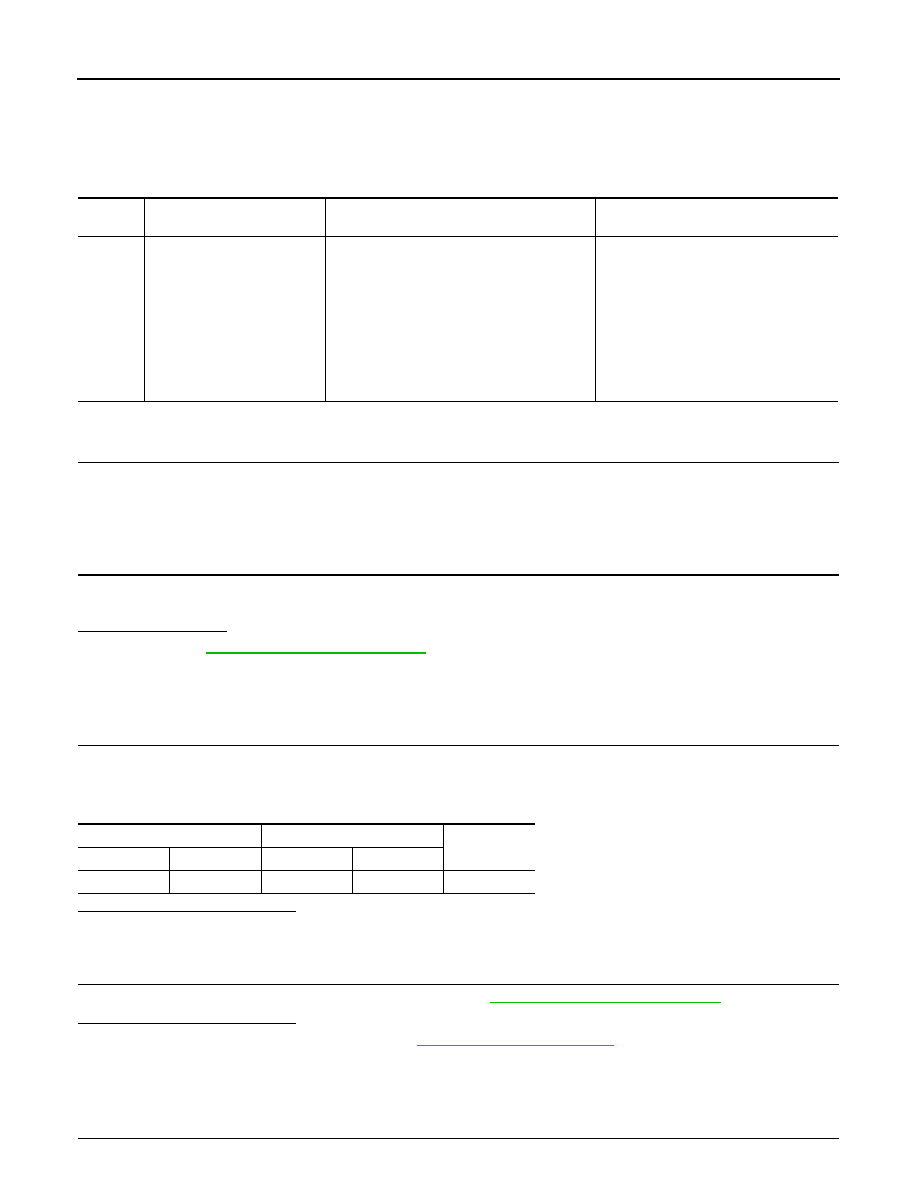
DTC
CONSULT screen terms
(Trouble diagnosis content)
DTC detection condition
Possible causes
P099C
SHIFT SOLENOID G
(Shift Solenoid G Control Cir-
cuit High)
The TCM high clutch & reverse brake solenoid
valve current monitor reading is 200 mA or
less continuously for 200 msec or more under
the following diagnosis conditions:
• Diagnosis conditions
- Solenoid valve output current: 750 mA or
more
- GND short diagnosis of the solenoid valve
circuit is not satisfied.
- TCM power supply voltage: More than 11 V
• Harness or connector
(High clutch & reverse brake solenoid
valve circuit is open or shorted to pow-
er supply)
• High clutch & reverse brake solenoid
valve
TCM
CVT unit
Continuity
Connector
Terminal
Connector
Terminal
F23
37
F46
23
Existed