Nissan Sentra. Manual - part 868
TM-108
< SYSTEM DESCRIPTION >
[CVT: RE0F11A]
DIAGNOSIS SYSTEM (TCM)
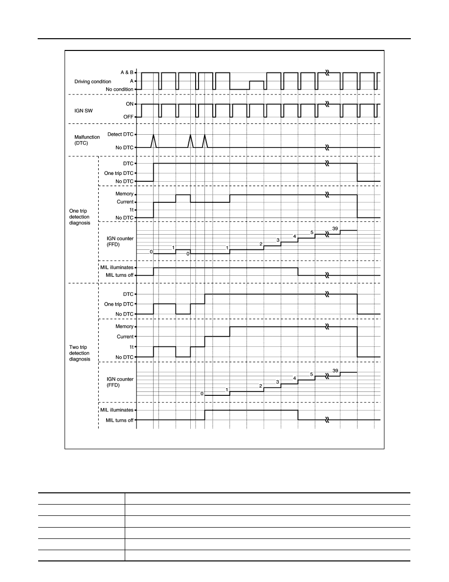
TIME CHART
CONSULT Function
INFOID:0000000009759362
APPLICABLE ITEM
JSDIA1868GB
Conditions
Function
All DTC Reading
Display all DTCs or diagnostic items that all ECUs are recording and judging.
Work Support
This mode enables a technician to adjust some devices faster and more accurately.
Self Diagnostic Results
Retrieve DTC from ECU and display diagnostic items.
Data Monitor
Monitor the input/output signal of the control unit in real time.
CAN Diagnosis
This mode displays a network diagnosis result about CAN by a diagram.