Nissan Sentra. Manual - part 866


  Index      Nissan     Nissan Sentra (2014 year) - Service and Repair Manual


Search            


Content   ..  864  865  866  867   ..


Nissan Sentra. Manual - part 866


TM-100

< SYSTEM DESCRIPTION >

[CVT: RE0F11A]

SYSTEM

For engine brake control on a downhill, the control can be stopped with CONSULT. 

Control In Acceleration

From change of the vehicle speed or accelerator pedal position, the acceleration request level of the driver or

driving scene is evaluated. In start or acceleration during driving, the gear shift characteristics with linearity of

revolution increase and vehicle speed increase are gained to improve the acceleration feel.

SELECT CONTROL
SELECT CONTROL : System Description

INFOID:0000000009759351
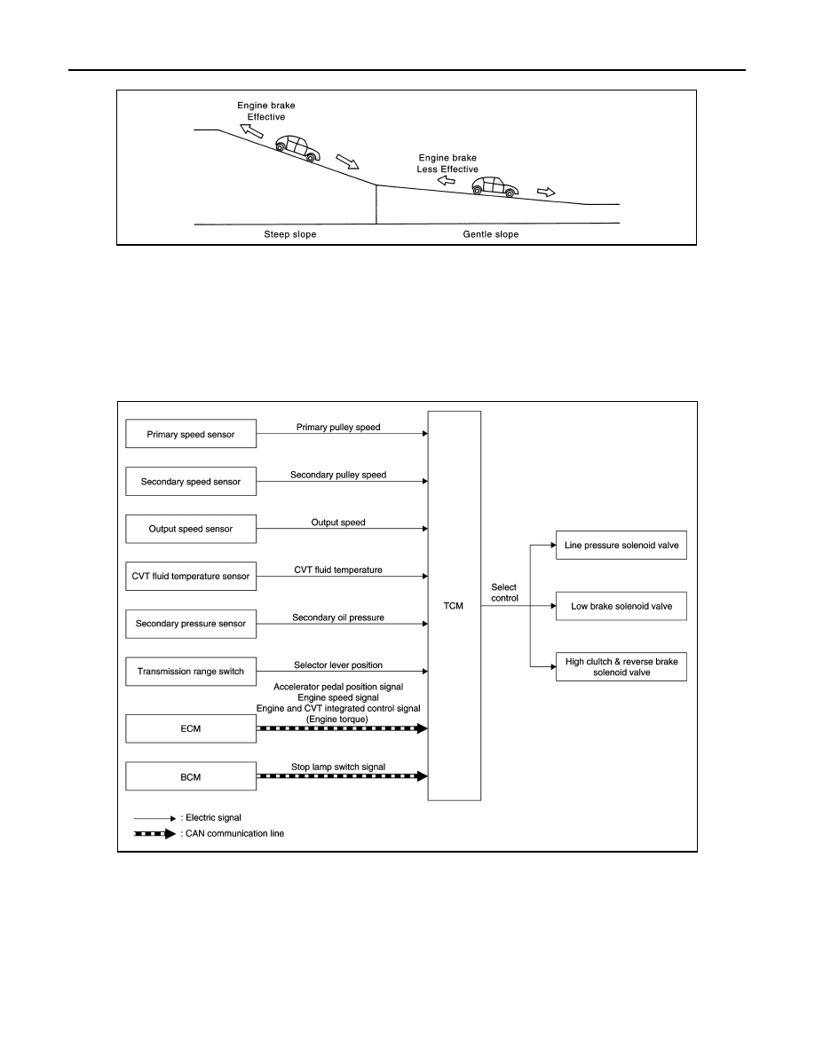
SYSTEM DIAGRAM

DESCRIPTION

Based on accelerator pedal angle, engine speed, primary pulley speed, and the secondary pulley speed, the

optimum operating pressure is set to reduce impact of a selector lever operation while shifting from “N” (“P”) to

“D” (“R”) position.

LOCK-UP CONTROL

JSDIA2060GB

JSDIA1862GB

SYSTEM

TM-101

< SYSTEM DESCRIPTION >

[CVT: RE0F11A]

C

E

F

G

H

I

J

K

L

M

A

B

TM

N

O

P

LOCK-UP CONTROL : System Description

INFOID:0000000009759352

SYSTEM DIAGRAM

DESCRIPTION

• Controls for improvement of the transmission efficiency by engaging the torque converter clutch in the

torque converter and eliminating slip of the converter. Achieves comfortable driving with slip control of the

torque converter clutch. 

• The oil pressure feed circuit for the torque converter clutch piston chamber is connected to the torque con-

verter clutch control valve. The torque converter clutch control valve is switched by the torque converter

clutch solenoid valve with the signal from TCM. This controls the oil pressure circuit, which is supplied to the

torque converter clutch piston chamber, to the release side or engagement side. 

• If the CVT fluid temperature is low or the vehicle is in fail-safe mode due to malfunction, lock-up control is

prohibited. 

Lock-up engagement

In lock-up engagement, the torque converter clutch solenoid valve makes the torque converter clutch control

valve locked up to generate the lock-up apply pressure. This pushes the torque converter clutch piston for

engagement. 

Lock-up release condition

In lock-up release, the torque converter clutch solenoid valve makes the torque converter clutch control valve

non-locked up to drain the lock-up apply pressure. This does not engage the torque converter clutch piston. 

IDLE NEUTRAL CONTROL

JSDIA1865GB

TM-102

< SYSTEM DESCRIPTION >

[CVT: RE0F11A]

SYSTEM

IDLE NEUTRAL CONTROL : System Description

INFOID:0000000009759353

SYSTEM DIAGRAM

DESCRIPTION

If a driver has no intention of starting the vehicle in D position, TCM operates the low brake solenoid valve and

controls the oil pressure of the low brake to be low pressure. Therefore, the low brake is in the release (slip)

JSDIA2535GB

SYSTEM

TM-103

< SYSTEM DESCRIPTION >

[CVT: RE0F11A]

C

E

F

G

H

I

J

K

L

M

A

B

TM

N

O

P

status and the power transmission route of transaxle is the same status as the N position. In this way, the tran-

saxle is in idling status and load to the engine can be reduced to improve fuel economy. 

Idle Neutral Control Start Condition

Idle neutral control is started when all of the following conditions are fulfilled. However, during idle neutral con-

trol, idle neutral control is stopped when any of the following conditions is not met.

NOTE:

Stops or prohibits the idle neutral control when the TCM and ECM detect that the vehicle is in one of the fol-

lowing conditions. 

• Engine coolant temperature and CVT fluid temperature are the specified temperature or more, or the speci-

fied temperature or less.

• When a transaxle malfunction occurs.

• When the vehicle detects DTC and is in the fail-safe mode.

• When idle speed increases due to heavy electric load*.

*: When any one of rear window defogger switch, A/C switch, headlamp, fog lamp is turned ON. In addition,

when the steering wheel is operated.

JSDIA2536GB

Driving environment 

: Flat road or road with mild gradient

Selector lever position

: “D” position

Vehicle speed

: 0 km/h (0 MPH)

Accelerator pedal position

: 0.0/8

Brake pedal

: Depressed

Engine speed

: Idle speed

Turn signal lamp/hazard signal lamp

: Not activated


Content   ..  864  865  866  867   ..