Nissan Sentra. Manual - part 833
EPS CONTROL UNIT
STC-39
< REMOVAL AND INSTALLATION >
C
D
E
F
H
I
J
K
L
M
A
B
STC
N
O
P
REMOVAL AND INSTALLATION
EPS CONTROL UNIT
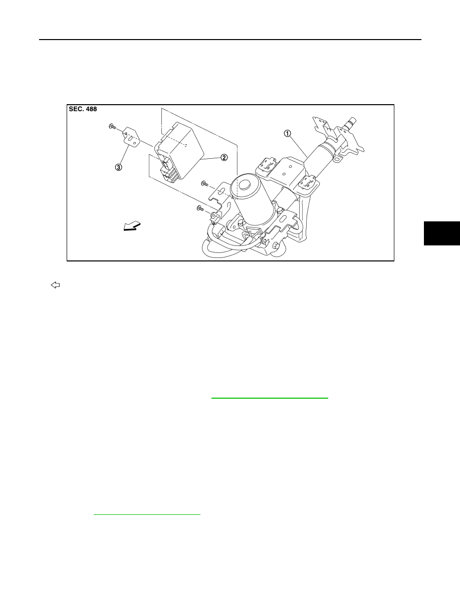
Exploded View
INFOID:0000000009757462
Removal and Installation
INFOID:0000000009757463
REMOVAL
CAUTION:
• Disconnect battery negative terminal before starting operations.
• Do not shock EPS control unit, e.g. drop or hit.
• Do not get EPS control unit wet with water or other liquid. Also, do not give EPS control unit a radical
temperature change to avoid getting water drops.
• Do not disassemble or remodel EPS control unit, EPS motor, torque sensor, harness and harness
connectors.
1. Remove steering column assembly. Refer to
ST-12, "Removal and Installation"
.
2. Disconnect EPS motor harness connector.
CAUTION:
Hold and pull the harness connector housing, not pulling harness, when disconnecting harness
connectors. Also, do not grip, collapse or apply excessive force to the harness connector.
3. Remove EPS control unit from steering column assembly.
4. Remove bracket plate from EPS control unit.
INSTALLATION
Installation is in the reverse order of removal.
• Check that harness is not damaged when installing EPS control unit. Also, check that EPS control unit is
installed without pinching harness or trapping foreign materials.
• After installing steering column assembly, perform self-diagnosis with CONSULT to ensure correct opera-
1.
Steering column assembly
2.
EPS control unit
3.
Bracket plate
Front
JPGIB0023ZZ