Nissan Sentra. Manual - part 720


  Index      Nissan     Nissan Sentra (2014 year) - Service and Repair Manual


Search            


Content   ..  718  719  720  721   ..


Nissan Sentra. Manual - part 720


PWO

POWER SOCKET

PWO-5

< REMOVAL AND INSTALLATION >

C

D

E

F

G

H

I

J

K

L

B

A

O

P

N

REMOVAL AND INSTALLATION

POWER SOCKET

Removal and Installation

INFOID:0000000009759549

FRONT CONSOLE POWER SOCKET

Removal

1. Remove the CVT/MT shift selector finisher. Refer to 

IP-14, "Exploded View"

.

2. Remove cap from the front console power socket.
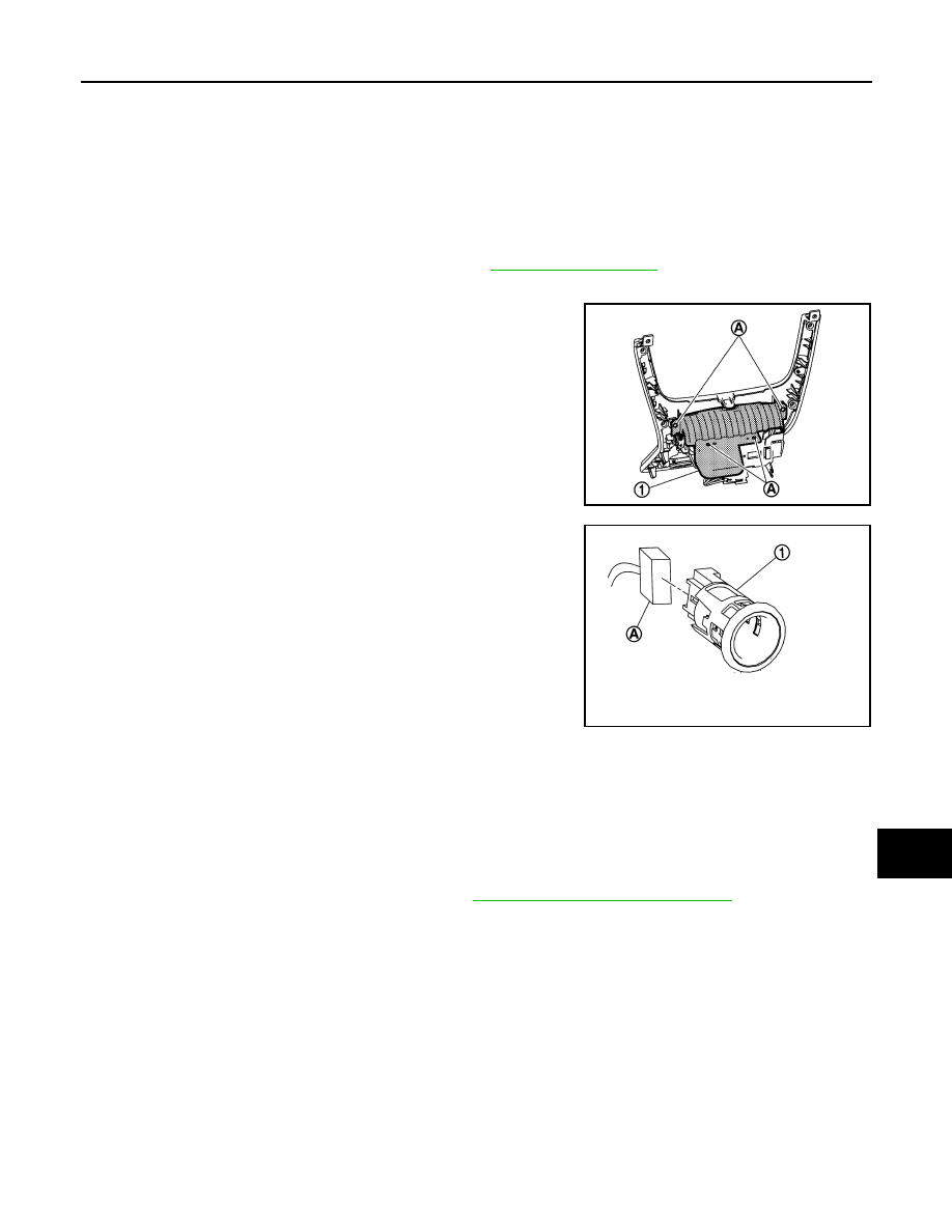
3. Remove the screws (A) and the storage bin (1).

4. Disconnect the harness connector (A) from the front console

power socket (1).

5. Release the power socket pawls from the back of the console finisher assembly and remove.

Installation

Installation is in the reverse order of removal.

CONSOLE POWER SOCKET (IF EQUIPPED)

Removal

1. Remove the center console rear finisher. Refer to 

IP-23, "Disassembly and Assembly"

.

2. Release the tabs and remove the center console rear finisher cover.
3. Disconnect the harness connectors from the power socket and the USB connector (if equipped).
4. Release the power socket pawls from the back of the center console rear finisher cover and remove.

Installation

Installation is in the reverse order of removal.

JSMIA1096ZZ

JSMIA1090ZZ

PWO-6

< SERVICE DATA AND SPECIFICATIONS (SDS) 

SERVICE DATA AND SPECIFICATIONS (SDS)

SERVICE DATA AND SPECIFICATIONS (SDS)

SERVICE DATA AND SPECIFICATIONS (SDS)

Power Socket

INFOID:0000000009759550

Rated voltage

DC 12 V

Maximum electric capacity

120 W or less (Total)

Maximum current

10 A or less (Total)

RAX-1

TRANSMISSION & DRIVELINE

C

E

F

G

H

I

J

K

L

M

SECTION 

RAX

A

B

RAX

N

O

P

CONTENTS

REAR AXLE

PRECAUTION ...............................................

2

PRECAUTIONS ...................................................

2

Precaution for Supplemental Restraint System 
(SRS) "AIR BAG" and "SEAT BELT PRE-TEN-
SIONER" .................................................................
..

2

General Precautions  .................................................

2

PREPARATION ............................................

3

PREPARATION ...................................................

3

Commercial Service Tools  ........................................

3

SYMPTOM DIAGNOSIS  ...............................

4

NOISE, VIBRATION AND HARSHNESS 
(NVH) TROUBLESHOOTING  .............................

4

NVH Troubleshooting Chart  ......................................

4

PERIODIC MAINTENANCE ..........................

5

REAR WHEEL HUB ...........................................

5

Inspection .................................................................

5

REMOVAL AND INSTALLATION ................

6

REAR WHEEL HUB ...........................................

6

Exploded View - Drum brake ....................................

6

Removal and Installation - Drum brake  ....................

6

Exploded View - Disc brake ......................................

7

Removal and Installation - Disc brake  ......................

7

Inspection .................................................................

8

SERVICE DATA AND SPECIFICATIONS 
(SDS) .............................................................

9

SERVICE DATA AND SPECIFICATIONS 
(SDS) ..................................................................

9

Wheel Bearing  ..........................................................

9

RAX-2

< PRECAUTION >

PRECAUTIONS

PRECAUTION

PRECAUTIONS

Precaution for Supplemental Restraint System (SRS) "AIR BAG" and "SEAT BELT 
PRE-TENSIONER"

INFOID:0000000010288840

The Supplemental Restraint System such as “AIR BAG” and “SEAT BELT PRE-TENSIONER”, used along

with a front seat belt, helps to reduce the risk or severity of injury to the driver and front passenger for certain

types of collision. Information necessary to service the system safely is included in the SR and SB section of

this Service Manual.

WARNING:

• To avoid rendering the SRS inoperative, which could increase the risk of personal injury or death in

the event of a collision which would result in air bag inflation, all maintenance must be performed by

an authorized NISSAN/INFINITI dealer.

• Improper maintenance, including incorrect removal and installation of the SRS, can lead to personal

injury caused by unintentional activation of the system. For removal of Spiral Cable and Air Bag

Module, see the SR section.

• Do not use electrical test equipment on any circuit related to the SRS unless instructed to in this

Service Manual. SRS wiring harnesses can be identified by yellow and/or orange harnesses or har-

ness connectors.

PRECAUTIONS WHEN USING POWER TOOLS (AIR OR ELECTRIC) AND HAMMERS

WARNING:

• When working near the Airbag Diagnosis Sensor Unit or other Airbag System sensors with the Igni-

tion ON or engine running, DO NOT use air or electric power tools or strike near the sensor(s) with a

hammer. Heavy vibration could activate the sensor(s) and deploy the air bag(s), possibly causing

serious injury.

• When using air or electric power tools or hammers, always switch the Ignition OFF, disconnect the

battery and wait at least three minutes before performing any service.

General Precautions

INFOID:0000000009756239

• When installing each rubber part, final tightening must be carried out under unladen condition* with

tires on ground.

*: Fuel, radiator coolant and engine oil full. Spare tire, jack, hand tools and mats in designated posi-

tions.

• After installing removed suspension parts, check wheel alignment.

• Do not jack up at the trailing arm and lateral link.


Content   ..  718  719  720  721   ..