Nissan Sentra. Manual - part 666
PCS
IPDM E/R (INTELLIGENT POWER DISTRIBUTION MODULE ENGINE ROOM)
PCS-17
< ECU DIAGNOSIS INFORMATION >
[IPDM E/R (WITH I-KEY)]
C
D
E
F
G
H
I
J
K
L
B
A
O
P
N
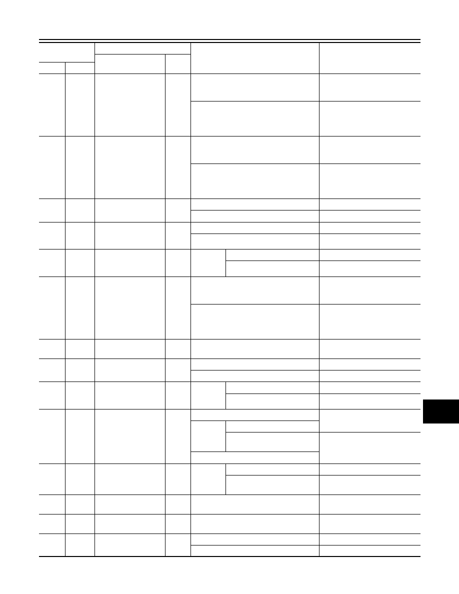
25
(G)
Ground
ECM relay power sup-
ply
Output
Ignition switch OFF
(More than a few seconds after turning igni-
tion switch OFF)
0 – 1 V
• Ignition switch ON
• Ignition switch OFF
(For a few seconds after turning ignition
switch OFF)
6 – 16 V
26
(P)
Ground
ECM relay power sup-
ply
Output
Ignition switch OFF
(More than a few seconds after turning igni-
tion switch OFF)
0 – 1 V
• Ignition switch ON
• Ignition switch OFF
(For a few seconds after turning ignition
switch OFF)
6 – 16 V
27
(L)
Ground
Front combination
lamp LH/RH
Output
Lighting switch OFF
0 – 1 V
Lighting switch 1ST
9 – 16 V
28
(R)
Ground
Rear combination
lamp, license plate
lamp and illuminations
Output
Lighting switch OFF
0 – 1 V
Lighting switch 1ST
9 – 16 V
29
(L)
Ground
Front wiper HI
Output
Ignition
switch
ON
Front wiper switch OFF
0 – 1 V
Front wiper switch HI
9 – 16 V
31
(O)
Ground
ECM relay control
Output
Ignition switch OFF
(More than a few seconds after turning igni-
tion switch OFF)
6 – 16 V
• Ignition switch ON
• Ignition switch OFF
(For a few seconds after turning ignition
switch OFF)
0 – 1 V
32
(Y)
Ground
ECM power supply
Output Ignition switch OFF
6 – 16 V
33
(V)
Ground
Illumination
Output
Lighting switch OFF
0 – 1 V
Lighting switch 1ST
9 – 16 V
35
(W)
Ground
Front wiper LO
Output
Ignition
switch
ON
Front wiper switch OFF
0 – 1 V
Front wiper switch LO
9 – 16 V
37
(SB)
Ground
Cranking request
Output
Ignition switch OFF
0 – 1 V
Ignition
switch
ON
Select lever P or N
Select lever in any position oth-
er than P or N
9 – 16 V
Engine running
39
(BR)
Ground
Front wiper stop posi-
tion
Input
Ignition
switch
ON
Front wiper stop position
0 – 1.5 V
Any position other than front
wiper stop position
9 – 16 V
40
(P)
Ground
CAN-L
Input/
Output
—
—
41
(L)
Ground
CAN-H
Input/
Output
—
—
42
(Y)
Ground
DTRL relay
Output
Lighting switch OFF
0 – 1 V
Lighting switch 1ST
9 – 16 V
Terminal NO.
(Wire color)
Description
Condition
Value
(Approx.)
Signal name
Input/
Output
+
–