Nissan Sentra. Manual - part 638


  Index      Nissan     Nissan Sentra (2014 year) - Service and Repair Manual


Search            


Content   ..  636  637  638  639   ..


Nissan Sentra. Manual - part 638


DOOR MIRROR

MIR-19

< REMOVAL AND INSTALLATION >

C

D

E

F

G

H

I

J

K

M

A

B

MIR

N

O

P

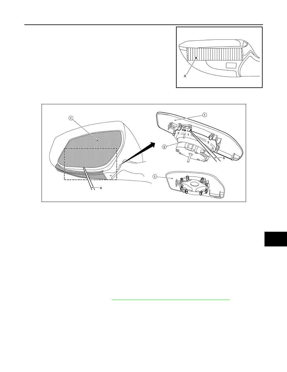
1. Put a strip of protective tape (A) on housing assembly.

2. Insert a suitable tool (A) into the recess at lower side between glass mirror (1) and actuator (2), and push

up pawls to remove glass mirror lower side in the order shown. 

3. Insert a suitable tool at (LH and RH) side between glass mirror and actuator, and push up pawls to remove

glass mirror (LH and RH) side. 

4. Disconnect door glass mirror heater harness connectors (if equipped).
5. Remove door glass mirror.

INSTALLATION

Installation is in the reverse order of removal.

CAUTION:

After installation, visually check that pawls are securely engaged.

DOOR MIRROR COVER
DOOR MIRROR COVER : Removal and Installation

INFOID:0000000009757799

REMOVAL

NOTE:

With side turn signal lamp shown, without is similar.
1. Remove door glass mirror. Refer to 

MIR-18, "GLASS MIRROR : Removal and Installation"

.

JMLIA3162ZZ

ALLIA1200ZZ

MIR-20

< REMOVAL AND INSTALLATION >

DOOR MIRROR

2. Using a suitable tool, disengage door mirror cover pawls to sep-

arate the door mirror cover (1) from the door mirror assembly

(2).

: Pawl

INSTALLATION

Installation is in the reverse order of removal.

CAUTION:

After installation, visually check that pawls are securely engaged.

ALLIA1201ZZ

DOOR MIRROR REMOTE CONTROL SWITCH

MIR-21

< REMOVAL AND INSTALLATION >

C

D

E

F

G

H

I

J

K

M

A

B

MIR

N

O

P

DOOR MIRROR REMOTE CONTROL SWITCH

Removal and Installation

INFOID:0000000009757800

REMOVAL

1. Remove the instrument finisher D. Refer to 

IP-14, "Exploded View"

.

2. Using suitable tool (A) release the pawls and remove the door mirror remote control switch (2) from the

switch bracket (1).

: Pawl

INSTALLATION

Installation is in the reverse order of removal.

ALLIA1202ZZ

MWI

MWI-1

DRIVER INFORMATION & MULTIMEDIA

C

D

E

F

G

H

I

J

K

L

M

B

SECTION 

MWI

A

O

P

CONTENTS

METER, WARNING LAMP & INDICATOR

PRECAUTION ...............................................

4

PRECAUTIONS ...................................................

4

Precaution for Supplemental Restraint System 
(SRS) "AIR BAG" and "SEAT BELT PRE-TEN-
SIONER" .................................................................
..

4

SYSTEM DESCRIPTION  ..............................

5

COMPONENT PARTS  ........................................

5

METER SYSTEM .........................................................

5

METER SYSTEM : Component Parts Location  ........

5

METER SYSTEM : Component Description  .............

6

SYSTEM ..............................................................

8

METER SYSTEM .........................................................

8

METER SYSTEM : System Diagram ........................

8

METER SYSTEM : System Description ....................

8

METER SYSTEM : Arrangement of Combination 
Meter .......................................................................
..

9

METER SYSTEM : Fail-Safe ....................................

9

SPEEDOMETER ........................................................

10

SPEEDOMETER : System Diagram  .......................

11

SPEEDOMETER : System Description ...................

11

TACHOMETER ..........................................................

11

TACHOMETER : System Diagram .........................

11

TACHOMETER : System Description .....................

11

ENGINE COOLANT TEMPERATURE GAUGE  ........

11

ENGINE COOLANT TEMPERATURE GAUGE : 
System Diagram ......................................................

11

ENGINE COOLANT TEMPERATURE GAUGE : 
System Description  .................................................

11

FUEL GAUGE ............................................................

11

FUEL GAUGE : System Diagram  ...........................

12

FUEL GAUGE : System Description  .......................

12

OIL PRESSURE WARNING LAMP ...........................

12

OIL PRESSURE WARNING LAMP : System Dia-
gram ........................................................................

12

OIL PRESSURE WARNING LAMP : System De-
scription ...................................................................

12

METER ILLUMINATION CONTROL  .........................

12

METER ILLUMINATION CONTROL : System Di-
agram ......................................................................

12

METER ILLUMINATION CONTROL : System De-
scription ...................................................................

12

INFORMATION DISPLAY ..........................................

13

INFORMATION DISPLAY : System Diagram ..........

13

INFORMATION DISPLAY : System Description  .....

13

COMPASS .................................................................

14

COMPASS : System Description .............................

14

DIAGNOSIS SYSTEM (COMBINATION 
METER) .............................................................

16

Description ...............................................................

16

CONSULT Function (METER/M&A) ........................

17

ECU DIAGNOSIS INFORMATION ..............

20

COMBINATION METER  ...................................

20

Reference Value ......................................................

20

Fail-Safe ..................................................................

25

DTC Index  ...............................................................

26

BCM (BODY CONTROL MODULE)  .................

27

List of ECU Reference .............................................

27

WIRING DIAGRAM ......................................

28

METER SYSTEM  ..............................................

28

Wiring Diagram ........................................................

28

COMPASS .........................................................

43

Wiring Diagram ........................................................

43

BASIC INSPECTION  ...................................

45


Content   ..  636  637  638  639   ..