Nissan Sentra. Manual - part 581


  Index      Nissan     Nissan Sentra (2014 year) - Service and Repair Manual


Search            


Content   ..  579  580  581  582   ..


Nissan Sentra. Manual - part 581


HAC-172

< DTC/CIRCUIT DIAGNOSIS >

[MANUAL AIR CONDITIONER]

BLOWER FAN ON SIGNAL

BLOWER FAN ON SIGNAL

Component Function Check

INFOID:0000000009757761

1.

CHECK BLOWER FAN ON SIGNAL

With CONSULT

1. Turn ignition switch ON.

2. Select “AIR CONDITIONER” of “BCM” using CONSULT.

3. Select “FAN ON SIG” in “DATA MONITOR” mode.

4. Check blower fan ON signal when the fan control dial is operated.

Is the inspection result normal?

YES

>> Inspection End.

NO

>> Refer to 

HAC-172, "Diagnosis Procedure"

.

Diagnosis Procedure

INFOID:0000000009757762

Regarding Wiring Diagram information, refer to 

HAC-145, "Wiring Diagram"

 or 

HAC-152, "Wiring Diagram"

.

1.

CHECK BLOWER FAN ON SIGNAL

1. Turn ignition switch OFF.

2. Disconnect A/C auto amp. harness connector.

3. Turn ignition switch ON.

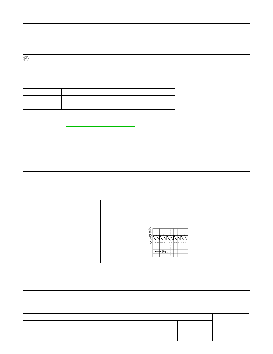
4. Check output waveform between A/C auto amp. and ground with using oscilloscope.

Is the inspection result normal?

YES

>> Replace A/C auto amp. Refer to 

HAC-189, "Removal and Installation"

.

NO

>> GO TO 2.

2.

CHECK BLOWER FAN ON SIGNAL CIRCUIT FOR OPEN

1. Turn ignition switch OFF.

2. Disconnect BCM connector.

3. Check continuity A/C auto amp. harness connector and BCM harness connector.

Monitor item

Condition

Status

FAN ON SIG

Blower motor

ON

On

OFF

OFF

+

Output waveform

A/C auto amp.

Connector

Terminal

M33 (with manual A/C)

M29 (without A/C)

14

Ground

PKIB4960J

A/C auto amp.

BCM

Continuity

Connector

Terminal

Connector

Terminal

M33 (with manual A/C)

14

M21 (without Intelligent Key system)

28

Yes

M29 (without A/C)

M84 (with Intelligent Key system)

BLOWER FAN ON SIGNAL

HAC-173

< DTC/CIRCUIT DIAGNOSIS >

[MANUAL AIR CONDITIONER]

C

D

E

F

G

H

J

K

L

M

A

B

HAC

N

O

P

Is the inspection result normal?

YES

>> GO TO 3.

NO

>> Repair harness or connector.

3.

CHECK BLOWER FAN ON SIGNAL CIRCUIT FOR SHORT

Check continuity between A/C auto amp. harness connector and ground.

Is the inspection result normal?

YES

>> Replace BCM. Refer to 

BCS-73, "Removal and Installation"

 (with Intelligent Key system) or 

BCS-

126, "Removal and Installation"

 (without Intelligent Key system).

NO

>> Repair harness or connector.

A/C auto amp.

Continuity

Connector

Terminal

M33 (with manual A/C)

14

Ground

No

M29 (without A/C)

HAC-174

< DTC/CIRCUIT DIAGNOSIS >

[MANUAL AIR CONDITIONER]

BLOWER MOTOR

BLOWER MOTOR

Diagnosis Procedure

INFOID:0000000009757763

Regarding Wiring Diagram information, refer to 

HAC-145, "Wiring Diagram"

 or 

HAC-152, "Wiring Diagram"

.

1.

CHECK FUSE

1. Turn ignition switch OFF.

2. Check following fuses.

-

10A fuse [No. 21, located in fuse block (J/B)]

-

15A fuses [Nos. 20 and 22, located in fuse block (J/B)]

NOTE:

Refer to 

PG-47, "Terminal Arrangement"

.

Is the inspection result normal?

YES

>> GO TO 2.

NO

>> Replace the blown fuse after repairing the affected circuit.

2.

CHECK BLOWER MOTOR POWER SUPPLY

1. Disconnect blower motor connector. 

2. Turn ignition switch ON.

3. Check voltage between blower motor harness connector and ground. 

Is the inspection result normal?

YES

>> GO TO 4.

NO

>> GO TO 3.

3.

CHECK BLOWER RELAY

1. Turn ignition switch OFF.

2. Check blower relay. Refer to 

HAC-177, "Component Inspection (Blower Motor Relay)"

.

Is the inspection result normal?

YES

>> Repair harness or connector between blower motor and fuse.

NO

>> Replace blower relay.

4.

CHECK BLOWER MOTOR CONTROL CIRCUIT

1. Turn ignition switch OFF.

2. Connect blower motor connector.

3. Disconnect variable blower control connector.

4. Turn ignition switch ON.

5. Check voltage between variable blower control harness connector and ground.

Is the inspection result normal?

YES

>> GO TO 6.

NO

>> GO TO 5.

5.

CHECK BLOWER MOTOR CONTROL CIRCUIT FOR OPEN

+

Voltage

Blower motor

Connector

Terminal

M62

1

Ground

Battery voltage

+

Voltage

Variable blower control

Connector

Terminal

M52

1

Ground

Battery voltage

BLOWER MOTOR

HAC-175

< DTC/CIRCUIT DIAGNOSIS >

[MANUAL AIR CONDITIONER]

C

D

E

F

G

H

J

K

L

M

A

B

HAC

N

O

P

1. Turn ignition switch OFF.

2. Disconnect blower motor connector.

3. Check continuity between variable blower control harness connector and blower motor harness connec-

tor. 

Is the inspection result normal?

YES

>> Replace blower motor. Refer to 

VTL-10, "Removal and Installation"

.

NO

>> Repair harness or connector.

6.

CHECK A/C AUTO AMP. IGNITION POWER SUPPLY

1. Turn ignition switch OFF.

2. Disconnect A/C auto amp.

3. Turn ignition switch ON.

4. Check voltage between A/C auto amp. harness connector and ground.

Is the inspection result normal?

YES

>> GO TO 7.

NO

>> Repair harness or connector between A/C auto amp. and fuse.

7.

CHECK VARIABLE BLOWER CONTROL IGNITION POWER SUPPLY

Check voltage between variable blower control harness connector and ground.

Is the inspection result normal?

YES

>> GO TO 8.

NO

>> Repair harness or connector between variable blower control and fuse.

8.

CHECK VARIABLE BLOWER CONTROL GROUND CIRCUIT FOR OPEN

1. Turn ignition switch OFF.

2. Check continuity between variable blower control harness connector and ground. 

Is the inspection result normal?

YES

>> GO TO 9.

NO

>> Repair harness or connector.

9.

CHECK VARIABLE BLOWER CONTROL CONTROL SIGNAL

1. Connect variable blower control connector and A/C auto amp. connector. 

2. Turn ignition switch ON.

3. Set air outlet to VENT. 

Variable blower control

Blower motor

Continuity

Connector

Terminal

Connector

Terminal

M52

1

M62

2

Existed

+

Voltage

A/C auto amp.

Connector

Terminal

M33 (with manual A/C)

21

Ground

Battery voltage

M29 (without A/C)

+

Voltage

Variable blower control

Connector

Terminal

M52

4

Ground

Battery voltage

Variable blower control

Continuity

Connector

Terminal

M52

3

Ground

Yes


Content   ..  579  580  581  582   ..