Nissan Sentra. Manual - part 537
HA-42
< REMOVAL AND INSTALLATION >
HEATING AND COOLING UNIT ASSEMBLY
HEATING AND COOLING UNIT ASSEMBLY
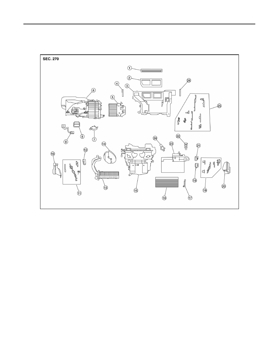
Exploded View
INFOID:0000000009756317
WITH AIR CONDITIONING
ALIIA0657ZZ
1.
Defroster seal
2.
Center ventilator seal
3.
Upper distribution module
4.
Side ventilator seal (LH)
5.
Blower motor
6.
Blower unit
7.
Intake door motor
8.
Power transistor
9.
Power transistor wiring harness
10. Front floor duct (LH)
11. Vent and defroster linkage
12. Mode door motor
13. Heater core
14. Heater core pipes grommet
15. Heating and cooling unit
16. In-cabin microfilter
17. In-cabin microfilter cover
18. Air mix door motor (LH) (Automatic A/C only)
19. Vent and defroster linkage
20. Front floor duct (RH)
21. Air mix door motor (RH)
22. Expansion valve
23. Evaporator
24. Aspirator (Automatic A/C only)
25. Vent and defroster linkage
26. Side ventilator seal (RH)