Nissan Sentra. Manual - part 502


  Index      Nissan     Nissan Sentra (2014 year) - Service and Repair Manual


Search            


Content   ..  500  501  502  503   ..


Nissan Sentra. Manual - part 502


TRANSVERSE LINK

FSU-11

< REMOVAL AND INSTALLATION >

C

D

F

G

H

I

J

K

L

M

A

B

FSU

N

O

P

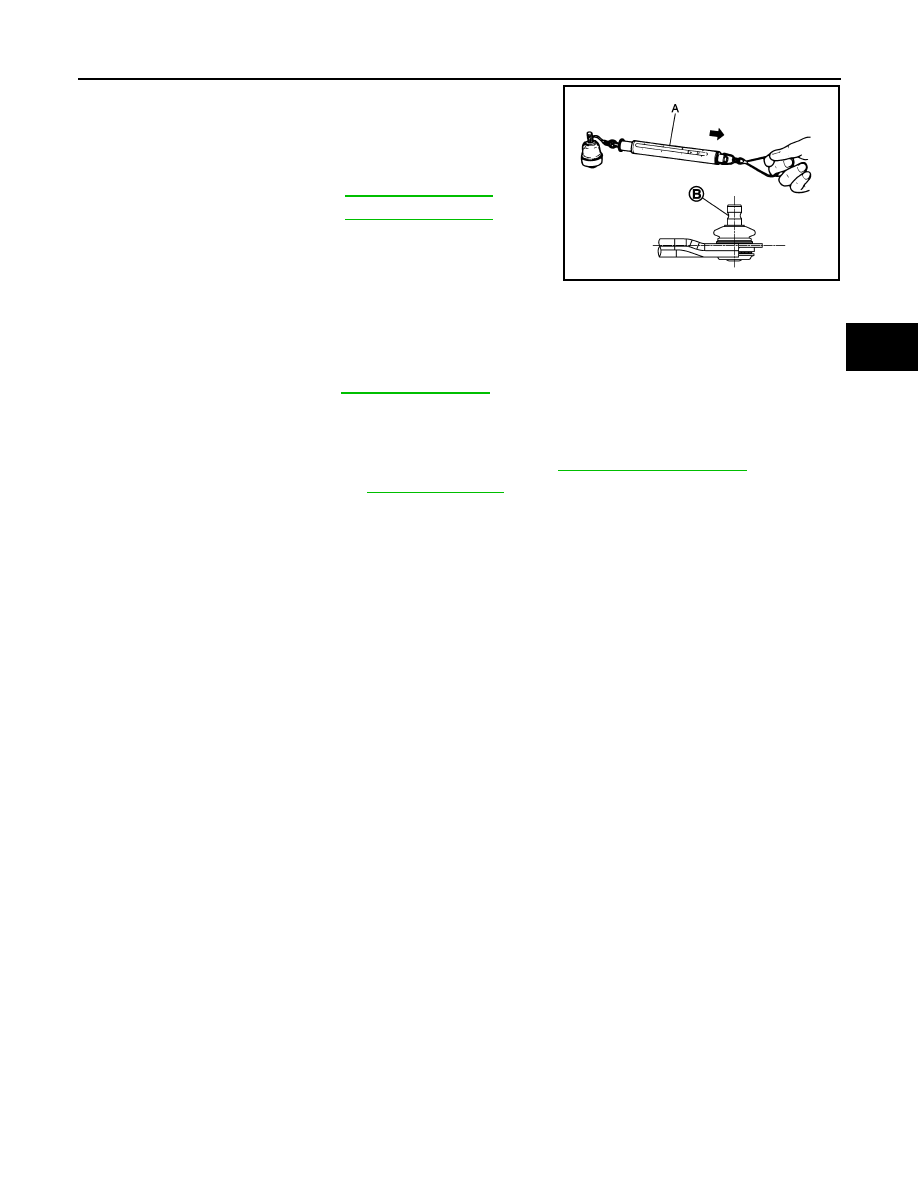
2. Hook the Tool (A) on the on ball joint (B). Confirm the measure-

ment value is within specifications when the ball joint begins

moving.

• If swing torque exceeds standard range, replace the transverse

link.

Axial End Play

1. Move the ball joint at least ten times by hand to check for smooth movement.
2. Move the tip of the ball joint in the axial direction to check for looseness.

• If the axial end play exceeds the standard value, replace the transverse link.

INSPECTION AFTER INSTALLATION

1. Check the neutral position of the steering angle sensor. Refer to 

BRC-54, "Work Procedure"

.

2. Check the wheel alignment. Refer to 

FSU-6, "Inspection"

.

Tool number

:  —  (J-44372)

Swing torque

: Refer to 

FSU-23, "Ball Joint"

.

Measurement on 
spring balance

: Refer to 

FSU-23, "Ball Joint"

JPEIA0138ZZ

Axial end play

Refer to 

FSU-23, "Ball Joint"

.

FSU-12

< REMOVAL AND INSTALLATION >

FRONT STABILIZER

FRONT STABILIZER

Exploded View

INFOID:0000000009758758

Removal and Installation

INFOID:0000000009758759

REMOVAL

1. Remove the wheel and tire using power tool. Refer to 

WT-47, "Exploded View"

.

2. Remove the nut and disconnect the stabilizer connecting rod from the stabilizer bar.
3. Remove the front suspension member. Refer to 

FSU-16, "Removal and Installation"

.

4. Remove the stabilizer clamp bolts (

).

5. Remove the stabilizer clamps.
6. Remove the stabilizer bushings.
7. Remove the stabilizer bar.
8. Inspect the components. Refer to 

FSU-13, "Inspection"

.

INSTALLATION

Installation is in the reverse order of removal.

1.

Stabilizer bar

2.

Stabilizer clamp

3.

Stabilizer bushing

4.

Stabilizer connecting rod

5.

Front coil spring and strut

6.

Front suspension member

Front

AWEIA0291ZZ

WEIA0182E

FRONT STABILIZER

FSU-13

< REMOVAL AND INSTALLATION >

C

D

F

G

H

I

J

K

L

M

A

B

FSU

N

O

P

• Install the stabilizer bushing with the slit (B) facing toward the front

of the vehicle (

).

• Install the stabilizer clamp with oblong hole (A) facing toward the

front of the vehicle (

).

• Install the stabilizer clamp bolts in the order of 1 to 5 as shown.

• To connect the stabilizer connecting rod (1), tighten the nut while

holding the hexagonal part (A) on the stabilizer connecting rod.

CAUTION:

Do not reuse stabilizer connecting rod nuts.

• Perform the final tightening of the nuts and bolts under unladen conditions with the tires on level ground.

• Complete the inspection. Refer to 

FSU-13, "Inspection"

.

Inspection

INFOID:0000000009758760

INSPECTION AFTER REMOVAL

Check the stabilizer bar, the stabilizer connecting rods, the stabilizer bushings, and the stabilizer clamps for

deformation, cracks or damage. Replace components if necessary.

INSPECTION AFTER INSTALLATION

1. Check the neutral position of the steering angle sensor. Refer to 

BRC-54, "Work Procedure"

.

2. Check the wheel alignment. Refer to 

FSU-6, "Inspection"

.

JPEIA0194ZZ

Manual tightening

: 1

Temporary tightening

: 2 

→ 3

Final tightening (Specified torque) 

: 4 

→ 5

: Front

JPEIA0245GB

JPEIA0252ZZ

FSU-14

< REMOVAL AND INSTALLATION >

STEERING KNUCKLE

STEERING KNUCKLE

Exploded View

INFOID:0000000009758761

Removal and Installation

INFOID:0000000009758762

REMOVAL

1. Remove the wheel and tire using power tool. Refer to 

WT-47, "Exploded View"

2. Remove the nut and disconnect the steering outer socket from the steering knuckle. Refer to 

ST-14,

"Removal and Installation"

.

3. Remove the nut and bolt from the lower ball joint. Disconnect the steering knuckle from the transverse

link.

4. Remove the wheel hub and bearing from the steering knuckle. Refer to 

FAX-8, "Removal and Installation"

.

5. Remove the splash guard from the steering knuckle.
6. Suspend the drive shaft with suitable wire. 
7. Remove the lower strut nuts and bolts (

). Refer to 

FSU-8,

"Exploded View"

.

8. Remove the steering knuckle.
9. Inspect the components. Refer to 

FSU-15, "Inspection"

.

INSTALLATION

Installation is in the reverse order of the removal.

CAUTION:

Do not reuse cotter pin.

1.

Steering knuckle

2.

Splash guard

3.

Wheel stud

4.

Wheel hub and bearing

5.

Disc brake rotor

6.

Wheel hub lock nut

7.

Nut retainer

8.

Cotter pin

AWDIA1076ZZ

WEIA0179E


Content   ..  500  501  502  503   ..