Nissan Sentra. Manual - part 500


  Index      Nissan     Nissan Sentra (2014 year) - Service and Repair Manual


Search            


Content   ..  498  499  500  501   ..


Nissan Sentra. Manual - part 500


PREPARATION

FSU-3

< PREPARATION >

C

D

F

G

H

I

J

K

L

M

A

B

FSU

N

O

P

PREPARATION

PREPARATION

Special Service Tools

INFOID:0000000009758747

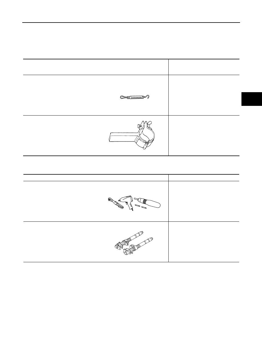
Commercial Service Tools

INFOID:0000000009758748

Tool number
(TechMate No.)
Tool name

Description

(J-44372)
Pull Gauge

Measuring ball joint swinging force

ST35652000
( — )
Strut attachment

Disassembling and assembling strut 

LST024

ZZA0807D

Tool name

Description

Power tool

Loosening nuts, screws and bolts

Spring compressor

Removing and installing coil spring

PIIB1407E

S-NT717

FSU-4

< SYMPTOM DIAGNOSIS >

NOISE, VIBRATION AND HARSHNESS (NVH) TROUBLESHOOTING

SYMPTOM DIAGNOSIS

NOISE, VIBRATION AND HARSHNESS (NVH) TROUBLESHOOTING

NVH Troubleshooting Chart

INFOID:0000000009758749

Use chart below to find the cause of the symptom. If necessary, repair or replace these parts.

×: Applicable

Reference

FSU-8

FSU-10

FSU-12

FS

U-

16

FSU-21

FSU-21

FSU-8

FSU-10

FSU-12

FS

U-

16

FSU-6

FSU-13

F

AX-5,

 "NVH T

ro

ub

les

ho

ot

ing

 Ch

art"

W

T-4

5, "

N

VH T

rou

bl

es

ho

oti

ng

 Cha

rt"

W

T-4

5, "

N

VH T

rou

bl

es

ho

oti

ng

 Cha

rt"

F

AX-5,

 "NVH T

ro

ub

les

ho

ot

ing

 Ch

art"

B

R

-7

, "

N

V

H

 T

rou

bl

es

ho

oti

ng

 Cha

rt"

ST

-9, 

"NVH T

ro

ubl

es

ho

ot

ing

 Cha

rt"

Possible cause and SUSPECTED PARTS

Im

p

rop

er i

ns

tal

la

tio

n, 

loo

sene

ss

S

hoc

k ab

so

rbe

r d

efo

rma

tio

n,

 da

ma

ge

 o

r de

fle

ct

ion

B

us

hin

or m

ou

nt

ing

 d

ete

rio

rati

on

P

art

s interference

S

pri

ng

 fat

ig

ue

S

us

pe

ns

ion

 lo

os

en

es

s

In

co

rrec

t wh

ee

l a

lig

nm

en

t

S

ta

bil

iz

er b

ar f

ati

gu

e

FRO

N

T A

X

L

E

TI

RE

ROAD  

 WHEEL

DRIV

E SHAFT

BR

AK

E

S

T

EERING

Symptom

FRONT SUSPENSION

Noise

×

×

×

×

×

×

×

×

×

×

×

×

Shake

×

×

×

×

×

×

×

×

×

×

×

Vibration

×

×

×

×

×

×

×

×

×

Shimmy

×

×

×

×

×

×

×

×

×

×

Shudder 

×

×

×

×

×

×

×

×

Poor quality ride or 
handling

×

×

×

×

×

×

×

×

×

×

FRONT SUSPENSION ASSEMBLY

FSU-5

< PERIODIC MAINTENANCE >

C

D

F

G

H

I

J

K

L

M

A

B

FSU

N

O

P

PERIODIC MAINTENANCE

FRONT SUSPENSION ASSEMBLY

Inspection

INFOID:0000000009758750

COMPONENT PART

Check the mounting conditions (looseness, backlash) of each component. Verify the component conditions

(wear, damage) are normal.

Ball Joint Axial End Play

1. Set the front wheels in a straight-ahead position.
2. Hold the axle side of the transverse link, and check the axial end

play by move the transverse link up and down.

CAUTION:

• Do not depress the brake pedal when measuring.

• Do not perform this inspection with the tires on the

ground.

• Be careful not to damage ball joint boot. Do not damage

the components by applying excessive force.

STRUT ASSEMBLY

Check for oil leaks or damage. Replace the parts if necessary.

Axial end play

Refer to 

FSU-23, "Ball Joint"

.

JSEIA0444ZZ

FSU-6

< PERIODIC MAINTENANCE >

WHEEL ALIGNMENT

WHEEL ALIGNMENT

Inspection

INFOID:0000000009758751

PRELIMINARY INSPECTION

WARNING:

Always adjust the wheel alignment with the vehicle on a flat surface.

NOTE:

If the wheel alignment is out of specification, inspect and replace any damaged or worn rear suspension parts

before making any adjustments.
1. Check and adjust the wheel alignment with the vehicle under unladen conditions. “Unladen conditions”

means that the fuel, engine coolant, and lubricants are full; the spare tire, jack, hand tools and mats are in

designated positions.

2. Check the tires for incorrect air pressure and excessive wear.
3. Check the wheels for run out and damage. Refer to 

WT-46, "Inspection"

.

4. Check the wheel bearing axial end play. Refer to 

FAX-6, "Inspection"

.

5. Check the shock absorbers for leaks or damage.
6. Check each mounting point of the suspension components for any excessive looseness or damage.
7. Check each link, arm, and the suspension member for any damage.
8. Check the vehicle height. Refer to 

FSU-23, "Wheelarch Height (Unladen*)"

.

GENERAL INFORMATION AND RECOMMENDATIONS

1. A Four-Wheel Thrust Alignment should be performed.

• This type of alignment is recommended for any NISSAN vehicle.

• The four-wheel “thrust” process helps ensure that the vehicle is properly aligned and the steering wheel

is centered.

• The alignment machine itself should be capable of accepting any NISSAN vehicle.

• The alignment machine should be checked to ensure that it is level.

2. Make sure the alignment machine is properly calibrated.

• Your alignment machine should be regularly calibrated in order to give correct information.

• Check with the manufacturer of your specific alignment machine for their recommended Service/Cali-

bration Schedule.

THE ALIGNMENT PROCESS

IMPORTANT: Use only the alignment specifications listed in this Service Manual. Refer to 

FSU-23, "Wheel

Alignment (Unladen*1)"

.

• When displaying the alignment settings, many alignment machines use “indicators”: (Green/red, plus or

minus, Go/No Go). Do NOT use these indicators.

- The alignment specifications programmed into your alignment machine that operate these indicators may

not be correct.

- This may result in an ERROR.

• Most camera-type alignment machines are equipped with both "Rolling Compensation" method and optional

"Jacking Compensation" method to "compensate" the alignment targets or head units.

"Rolling Compensation" is the preferred method.

- If using the "Rolling Compensation" method, after installing the alignment targets or head units, push or pull

on the rear wheel to move the vehicle. Do not push or pull the vehicle body.

- If using the "Jacking Compensation" method, after installing the alignment targets or head units, raise the

vehicle and rotate the wheels 1/2 turn both ways.

NOTE:

Do not use the "rolling Compensation" method if you are using sensor-type alignment equipment. 

• Follow all instructions for the alignment machine you're using for more information.

CAMBER, CASTER AND KINGPIN INCLINATION ANGLES INSPECTION

• Camber, caster, kingpin inclination angles cannot be adjusted.

• Before inspection, set the front wheels onto a turning radius gauge. Set the rear wheels onto a pad that has

the same height so the vehicle will remain horizontal.

TOTAL TOE-IN INSPECTION

Measure the total toe-in using the following procedure.


Content   ..  498  499  500  501   ..