Nissan Sentra. Manual - part 472


  Index      Nissan     Nissan Sentra (2014 year) - Service and Repair Manual


Search            


Content   ..  470  471  472  473   ..


Nissan Sentra. Manual - part 472


HEADLAMP (LO) CIRCUIT

EXL-91

< DTC/CIRCUIT DIAGNOSIS >

C

D

E

F

G

H

I

J

K

M

A

B

EXL

N

O

P

Is the inspection result normal?

YES

>> GO TO 4.

NO

>> GO TO 3.

3.

CHECK HEADLAMP (LO) CIRCUIT FOR OPEN

1. Turn the ignition switch OFF.

2. Disconnect IPDM E/R connector.

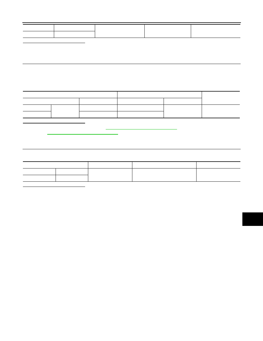
3. Check continuity between the IPDM E/R harness connector and the front combination lamp harness con-

nector.

Is the inspection result normal?

YES

>> Replace IPDM E/R. Refer to 

PCS-30, "Removal and Installation"

 (with Intelligent Key system) or

PCS-58, "Removal and Installation"

 (without Intelligent Key system).

NO

>> Repair or replace the harness or connector.

4.

CHECK FRONT COMBINATION LAMP (LO) GROUND CIRCUIT

Check continuity between the front combination lamp harness connector and ground.

Is the inspection result normal?

YES

>> Inspect the headlamp bulb.

NO

>> Repair or replace the harness or connector.

RH

E20

1

Ground

Battery voltage

LH

E21

IPDM E/R

Front combination lamp

Continuity

Connector

Terminal

Connector

Terminal

RH

E43

8

E20

1

Yes

LH

7

E21

Connector

Terminal

Continuity

RH

E20

5

Ground

Yes

LH

E21

EXL-92

< DTC/CIRCUIT DIAGNOSIS >

DAYTIME LIGHT RELAY CIRCUIT

DAYTIME LIGHT RELAY CIRCUIT

Description

INFOID:0000000009757513

The BCM sends a daytime light request to the IPDM E/R via the CAN communication lines. The power flows

through fuse 29 located in fuse block J/B to the daytime light relay coil. When the IPDM E/R operates the day-

time light relay, power is sent to the daytime lamps.

Diagnosis Procedure

INFOID:0000000009757514

Regarding Wiring Diagram information, refer to 

EXL-38, "Wiring Diagram"

.

1.

CHECK DAYTIME LIGHT RELAY VOLTAGE SUPPLY

1. Turn the ignition switch OFF.

2. Remove the daytime light relay.

3. Check the voltage between the daytime light relay harness connector and ground.

Is the inspection result normal?

YES

>> GO TO 3.

NO

>> GO TO 2.

2.

CHECK DAYTIME LIGHT RELAY FUSE

Check that the following fuses are not blown.

Is the fuse blown?

YES

>> Replace the blown fuse after repairing the affected circuit.

NO

>> Repair or replace the harness or connector.

3.

CHECK DAYTIME LIGHT RELAY CONTROL CIRCUIT

1. Check continuity between the IPDM E/R harness connector and the daytime light relay harness connec-

tor.

2. Check continuity between the daytime light relay harness connector and ground.

Is the inspection result normal?

YES

>> GO TO 4.

NO

>> Repair or replace the harness or connector.

4.

CHECK DAYTIME LIGHT RELAY

Check the daytime light relay. Refer to 

EXL-93, "Component Inspection"

.

Daytime light relay

(

−)

Voltage

Connector

Terminal

E30

2

Ground

Battery voltage

5

Unit

Location

Fuse No.

Capacity

Daytime light 

Fuse block J/B

29

10A

Daytime light relay

IPDM E/R

Continuity

Connector

Terminal

Connector

Terminal

E30

1

E46

42

Yes

Connector

Terminal

Continuity

E30

1

Ground

No

DAYTIME LIGHT RELAY CIRCUIT

EXL-93

< DTC/CIRCUIT DIAGNOSIS >

C

D

E

F

G

H

I

J

K

M

A

B

EXL

N

O

P

Is the inspection result normal?

YES

>> GO TO 5.

NO

>> Replace relay.

5.

CHECK DAYTIME LIGHT CIRCUIT (OPEN OR SHORT TO GROUND)

1. Check continuity between the daytime light relay harness connector and the front combination lamp har-

ness connector.

2. Check continuity between the daytime light relay harness connector and ground.

Is the inspection result normal?

YES

>> GO TO 6.

NO

>> Repair or replace the harness or connector.

6.

CHECK DAYTIME LIGHT GROUND CIRCUIT FOR OPEN

1. Disconnect front combination lamp connector in question.

2. Check continuity between the front combination lamp connector and ground.

Is the inspection result normal?

YES

>> Inspect daytime light bulb.

NO

>> Repair or replace the harness or connector.

Component Inspection

INFOID:0000000009757515

1.

 CHECK DAYTIME LIGHT RELAY

1. Turn ignition switch OFF.

2. Remove daytime light relay.

3. Check the continuity between daytime light relay terminals 3 and 5 when voltage is supplied between ter-

minals 1 and 2.

Is the inspection result normal?

YES

>> Inspection End.

NO

>> Replace daytime light relay.

Daytime light relay

Front combination lamp

Continuity

Connector

Terminal

Connector

Terminals

E30

3

LH

E21

3, 8

Yes

RH

E20

Daytime light relay

(

−)

Continuity

Connector

Terminal

E30

3

Ground

No

Connector

Terminal

Continuity

LH E21

7

Ground

Yes

RH E20

Terminals

Condition

Continuity

3 and 5

12V direct current supply between terminals 1 and 2

Yes

No current supply

No

EXL-94

< DTC/CIRCUIT DIAGNOSIS >

FRONT FOG LAMP CIRCUIT

FRONT FOG LAMP CIRCUIT

Description

INFOID:0000000009757516

The IPDM E/R (intelligent power distribution module engine room) controls the front fog lamp relay based on

inputs from the BCM over the CAN communication lines. When the front fog lamp relay is energized, power

flows from the front fog lamp relay in the IPDM E/R to the front fog lamps. 

Component Function Check

INFOID:0000000009757517

1.

CHECK FRONT FOG LAMP OPERATION

WITHOUT CONSULT

1. Activate IPDM E/R auto active test. Refer to 

EXL-24, "Diagnosis Description"

 (with Intelligent Key system)

or 

EXL-28, "Diagnosis Description"

 (without Intelligent Key system).

2. Check that the front fog lamp is turned ON.

WITH CONSULT

1. Select EXTERNAL LAMP of IPDM E/R active test item.

2. While operating the test items, check that the front fog lamp is turned ON.

Is the inspection result normal?

YES

>> Front fog lamp circuit is normal.

NO

>> Refer to 

EXL-94, "Diagnosis Procedure"

Diagnosis Procedure

INFOID:0000000009757518

Regarding Wiring Diagram information, refer to 

EXL-53, "Wiring Diagram"

.

1.

CHECK FRONT FOG LAMP FUSE

1. Turn the ignition switch OFF.

2. Check that the following fuse is not blown.

Is the fuse blown?

YES

>> Replace the fuse after repairing the affected circuit.

NO

>> GO TO 2.

2.

CHECK FRONT FOG LAMP OUTPUT VOLTAGE

CONSULT

1. Disconnect the front fog lamp harness connector in question.

2. Turn the ignition switch ON.

3. Turn the front fog lamps ON.

4. Check the voltage between the front fog lamp harness connector and ground.

Is the inspection result normal?

YES

>> GO TO 4.

FOG

: Front fog lamp ON

OFF

: Front fog lamp OFF

Unit

Location

Fuse No.

Capacity

Front fog lamp 

IPDM E/R

40

15A

(+)

(

−)

Voltage

Connector

Terminal

LH

E27

1

Ground

Battery voltage

RH

E28


Content   ..  470  471  472  473   ..