Nissan Sentra. Manual - part 416
EC-360
< DTC/CIRCUIT DIAGNOSIS >
[MRA8DE]
P1078 EVT CONTROL POSITION SENSOR
3.
CHECK EVT CONTROL POSITION SENSOR GROUND CIRCUIT
1. Turn ignition switch OFF.
2. Disconnect ECM harness connector.
3. Check the continuity between EVT control position sensor harness connector and ECM harness connec-
tor.
4. Also check harness for short to power.
Is the inspection result normal?
YES
>> GO TO 4.
NO
>> Repair or replace error-detected parts.
4.
CHECK EVT CONTROL POSITION SENSOR INPUT SIGNAL CIRCUIT
1. Disconnect ECM harness connector.
2. Check the continuity between EVT control position sensor harness connector and ECM harness connec-
tor.
3. Also check harness for short to ground and to power.
Is the inspection result normal?
YES
>> GO TO 5.
NO
>> Repair or replace error-detected parts.
5.
CHECK EVT CONTROL POSITION SENSOR
Check the EVT control position sensor. Refer to
EC-360, "Component Inspection (EVT Control Position Sen-
Is the inspection result normal?
YES
>> GO TO 6.
NO
>> Replace EVT control position sensor. Refer to
EM-60, "Removal and Installation"
.
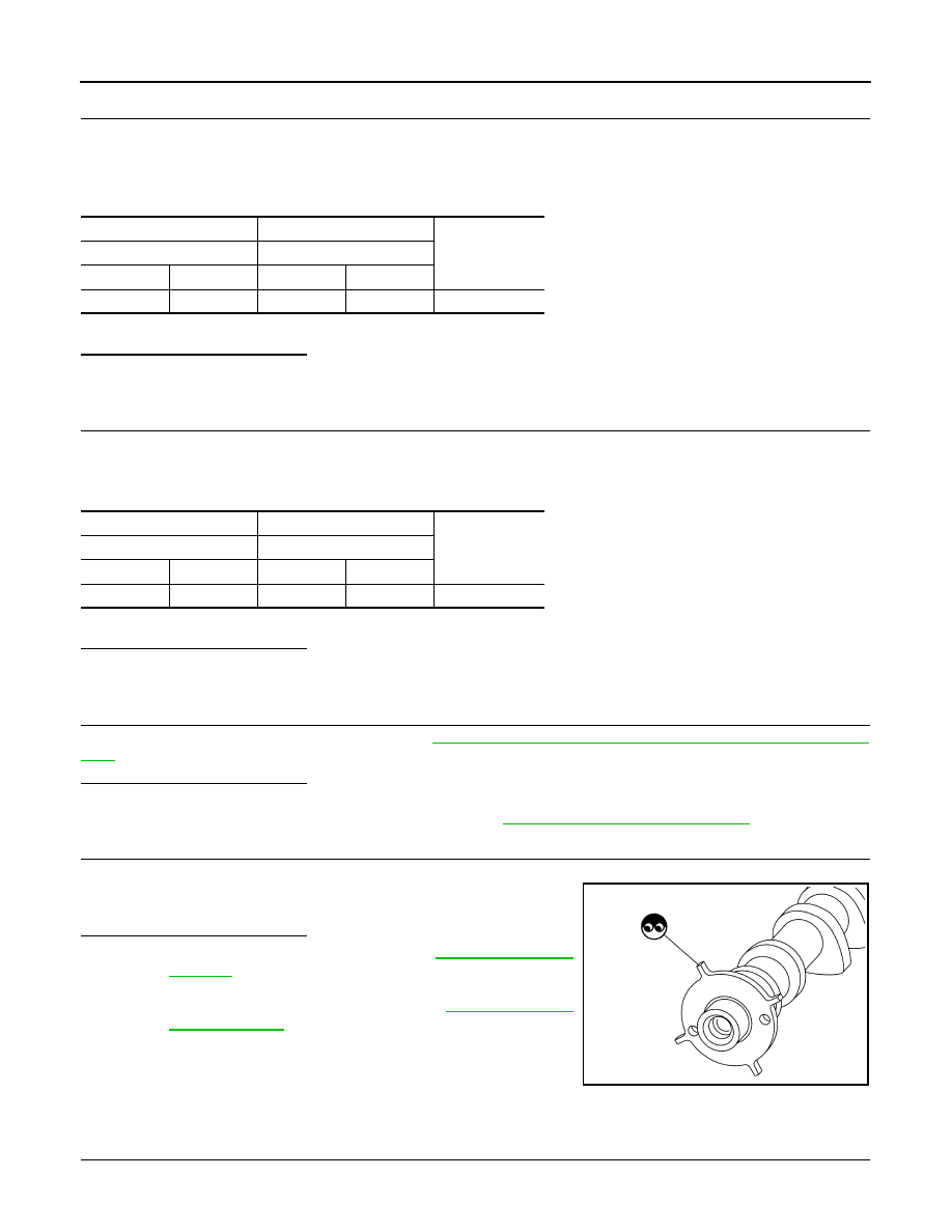
6.
CHECK CAMSHAFT (EXT)
Check the following.
• Accumulation of debris to the signal plate of camshaft rear end
• Chipping signal plate of camshaft rear end
Is the inspection result normal?
YES
>> Check intermittent incident. Refer to
NO
>> Remove debris and clean the signal plate of camshaft
rear end or replace camshaft. Refer to
.
Component Inspection (EVT Control Position Sensor)
INFOID:0000000009758612
1.
EXHAUST VALVE TIMING (EVT) CONTROL POSITION SENSOR-1
1. Turn ignition switch OFF.
+
−
Continuity
EVT control position sensor
ECM
Connector
Terminal
Connector
Terminal
F57
2
F24
42
Existed
+
−
Continuity
EVT control position sensor
ECM
Connector
Terminal
Connector
Terminal
F57
3
F24
43
Existed
JSBIA0600ZZ