Nissan Sentra. Manual - part 415


  Index      Nissan     Nissan Sentra (2014 year) - Service and Repair Manual


Search            


Content   ..  413  414  415  416   ..


Nissan Sentra. Manual - part 415


EC-356

< DTC/CIRCUIT DIAGNOSIS >

[MRA8DE]

P0850 PNP SWITCH

Follow the procedure “With CONSULT” above.
Is 1st trip DTC detected?

YES

>> Proceed to 

EC-356, "Diagnosis Procedure"

.

NO

>> INSPECTION END

Component Function Check

INFOID:0000000009758608

1.

CHECK PNP SIGNAL FUNCTION

With CONSULT

1. Turn ignition switch ON.

2. Select “P/N POSI SW” in “DATA MONITOR” mode of “ENGINE” using CONSULT. Then check the “P/N

POSI SW” signal as per the following conditions.

Is the inspection result normal?

YES

>> GO TO 2.

NO

>> Proceed to 

EC-356, "Diagnosis Procedure"

.

2.

PERFORM COMPONENT FUNCTION CHECK

1. Turn ignition switch ON.

2. Check the voltage between ECM harness connector and ground as per the following conditions.

Is the inspection result normal?

YES

>> INSPECTION END

NO

>> Proceed to 

EC-356, "Diagnosis Procedure"

.

Diagnosis Procedure

INFOID:0000000009758609

1.

INSPECTION START

Check which type of transmission the vehicle is equipped with.
Which type of transmission?

CVT models>>GO TO 2.

M/T models>>GO TO 6.

2.

CHECK TRANSMISSION RANGE SWITCH POWER SUPPLY

1. Turn ignition switch OFF.

2. Disconnect transmission range switch harness connector.

3. Turn ignition switch ON.

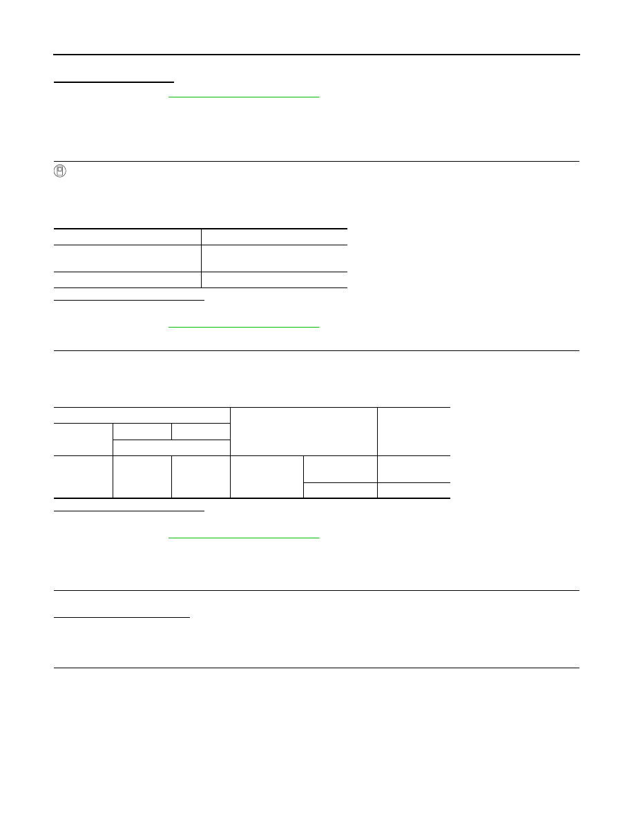
4. Check the voltage between transmission range switch harness connector and ground.

Selector lever position

Indication

N or P position (CVT)
Neutral position (M/T)

ON

Except above position

OFF

ECM

Condition

Voltage

(Approx.)

Connector

+

Terminal

E16

117

128

Selector lever

• P  or  N  (CVT)
• Neutral (M/T)

Battery voltage

Except above

0 V

P0850 PNP SWITCH

EC-357

< DTC/CIRCUIT DIAGNOSIS >

[MRA8DE]

C

D

E

F

G

H

I

J

K

L

M

A

EC

N

P

O

Is the inspection result normal?

YES

>> GO TO 4.

NO

>> GO TO 3.

3.

CHECK TRANSMISSION RANGE SWITCH POWER SUPPLY CIRCUIT

1. Turn ignition switch OFF.

2. Disconnect IPDM E/R harness connector.

3. Check the continuity between transmission range switch harness connector and IPDM E/R harness con-

nector.

4. Also check harness for short to ground.
Is the inspection result normal?

YES

>> Perform the trouble diagnosis for power supply circuit.

NO

>> Repair or replace error-detected parts.

4.

CHECK TRANSMISSION RANGE SWITCH SIGNAL CIRCUIT

1. Turn ignition switch OFF.

2. Disconnect ECM harness connector.

3. Check the continuity between transmission range switch harness connector and ECM harness connector.

4. Also check harness for short to ground and to power.
Is the inspection result normal?

YES

>> GO TO 5.

NO

>> Repair or replace error-detected parts.

5.

CHECK TRANSMISSION RANGE SWITCH

Check the transmission range switch. Refer to 

TM-165, "Component Inspection"

.

Is the inspection result normal?

YES

>> Check intermittent incident. Refer to 

GI-39, "Intermittent Incident"

.

NO

>> Replace transaxle assembly. Refer to 

TM-283, "Removal and Installation"

.

6.

CHECK PARK/NEUTRAL POSITION (PNP) SWITCH POWER SUPPLY

1. Turn ignition switch OFF.

2. Disconnect PNP switch harness connector.

3. Turn ignition switch ON.

4. Check the voltage between PNP switch harness connector and ground.

+

Voltage

Transmission range switch

Connector

Terminal

F26

7

Ground

Battery voltage

+

Continuity

Transmission range switch

IPDM E/R

Connector

Terminal

Connector

Terminal

F26

7

E43

14

Existed

+

Continuity

Transmission range switch

ECM

Connector

Terminal

Connector

Terminal

F26

10

E16

117

Existed

EC-358

< DTC/CIRCUIT DIAGNOSIS >

[MRA8DE]

P0850 PNP SWITCH

Is the inspection result normal?

YES

>> GO TO 7.

NO

>> Perform the trouble diagnosis for power supply circuit.

7.

CHECK PNP SWITCH INPUT SIGNAL CIRCUIT

1. Turn ignition switch OFF.

2. Disconnect ECM harness connector.

3. Check the continuity between PNP switch harness connector and ECM harness connector.

4. Also check harness for short to ground and to power.
Is the inspection result normal?

YES

>> GO TO 8.

NO

>> Repair or replace error-detected parts.

8.

CHECK PNP SWITCH

Check the PNP switch. Refer to 

TM-17, "PARK/NEUTRAL POSITION (PNP) SWITCH : Component Inspec-

tion"

.

Is the inspection result normal?

YES

>> Check intermittent incident. Refer to 

GI-39, "Intermittent Incident"

.

NO

>> Replace PNP switch. Refer to 

TM-21, "Removal and Installation"

.

+

Voltage

PNP switch

Connector

Terminal

F52

2

Ground

Battery voltage

+

Continuity

PNP switch

ECM

Connector

Terminal

Connector

Terminal

F52

3

E16

117

Existed

P1078 EVT CONTROL POSITION SENSOR

EC-359

< DTC/CIRCUIT DIAGNOSIS >

[MRA8DE]

C

D

E

F

G

H

I

J

K

L

M

A

EC

N

P

O

P1078 EVT CONTROL POSITION SENSOR

DTC Logic

INFOID:0000000009758610

DTC DETECTION LOGIC

DTC CONFIRMATION PROCEDURE

1.

PRECONDITIONING

If DTC Confirmation Procedure has been previously conducted, always perform the following procedure

before conducting the next test. 

1. Turn ignition switch OFF and wait at least 10 seconds.

2. Turn ignition switch ON.

3. Turn ignition switch OFF and wait at least 10 seconds.

>> GO TO 2.

2.

PERFORM DTC CONFIRMATION PROCEDURE

1. Start engine and let it idle for 10 seconds.

2. Check 1st trip DTC.
Is 1st trip DTC detected?

YES

>> Proceed to 

EC-359, "Diagnosis Procedure"

.

NO

>> INSPECTION END

Diagnosis Procedure

INFOID:0000000009758611

1.

CHECK EXHAUST VALVE TIMING (EVT) CONTROL POSITION SENSOR POWER SUPPLY

1. Turn ignition switch OFF.

2. Disconnect exhaust valve timing (EVT) control position sensor harness connector.

3. Turn ignition switch ON.

4. Check the voltage between EVT control position sensor harness connector and ground.

Is the inspection result normal?

YES

>> GO TO 3.

NO

>> GO TO 2.

2.

CHECK SENSOR POWER SUPPLY 2 CIRCUIT

Check sensor power supply 2 circuit. Refer to 

EC-444, "Diagnosis Procedure"

.

Is inspection result normal?

YES

>> Perform the trouble diagnosis for power supply circuit.

NO

>> Repair or replace error-detected parts.

DTC No.

CONSULT screen terms

(Trouble diagnosis content)

DTC detecting condition

Possible cause

P1078

EXH TIM SEN/CIRC-B1
(Exhaust valve timing con-
trol position sensor circuit 
bank 1)

An excessively high or low voltage from 
the sensor is sent to ECM.

• Harness or connectors

(Exhaust valve timing control position sen-
sor circuit is open or shorted)

• Accumulation of debris to the signal pick-up 

portion of the camshaft

• Exhaust valve timing control position sen-

sor

• Sensor power supply 2 circuit

+

Voltage

(Approx.)

EVT control position sensor

Connector

Terminal

F57

1

Ground

5.0 V


Content   ..  413  414  415  416   ..