Nissan Sentra. Manual - part 338


  Index      Nissan     Nissan Sentra (2014 year) - Service and Repair Manual


Search            


Content   ..  336  337  338  339   ..


Nissan Sentra. Manual - part 338


EC-48

< SYSTEM DESCRIPTION >

[MRA8DE]

SYSTEM

SYSTEM DESCRIPTION

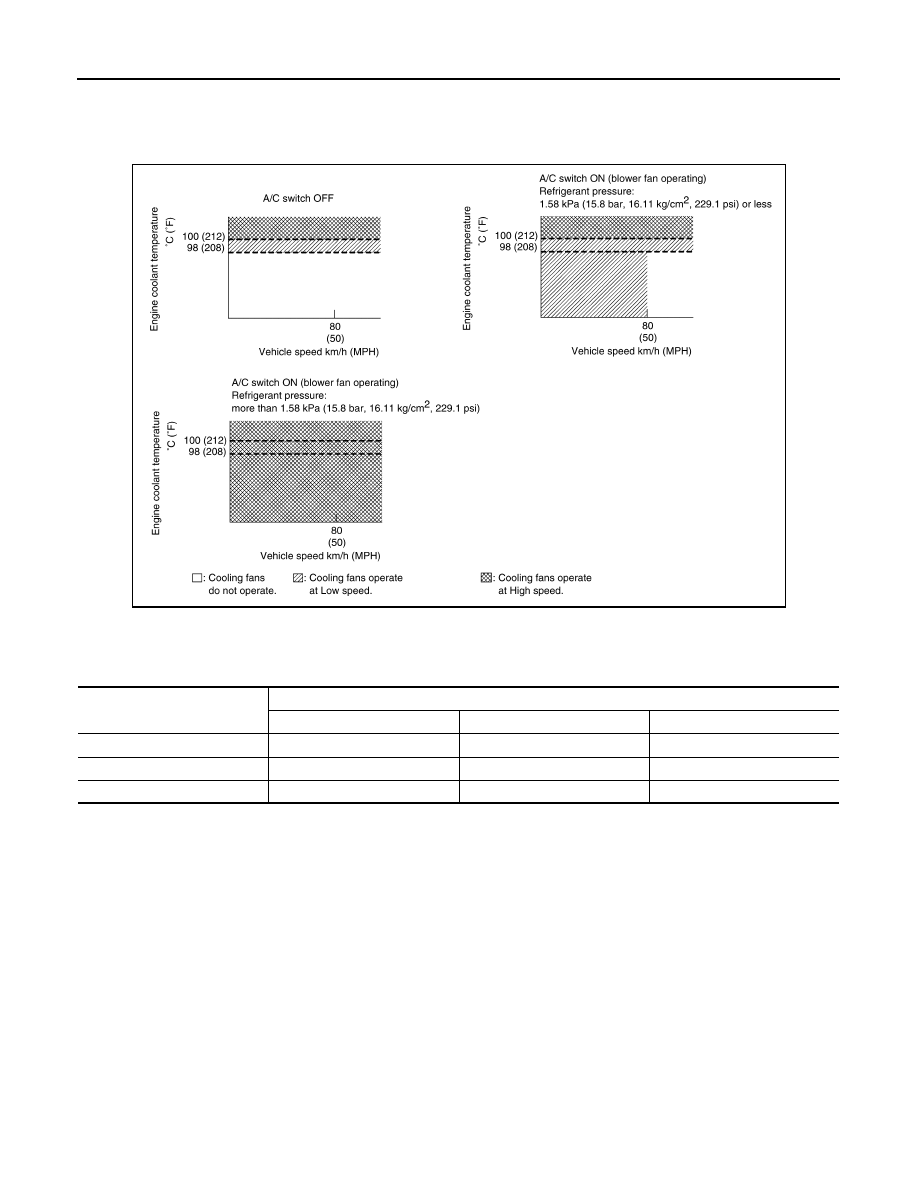
ECM controls cooling fan speed corresponding to vehicle speed, engine coolant temperature, refrigerant pres-

sure, air conditioner ON signal. Then control system has 3-step control [HIGH/LOW/OFF].

Cooling Fan Operation

Cooling Fan Relay Operation

When IPDM E/R recieves a cooling fan speed request signal, IPDM E/R controls the cooling fan ralay 1, 2 and

3.

STARTER MOTOR DRIVE CONTROL
STARTER MOTOR DRIVE CONTROL : System Description

INFOID:0000000009758372

SYSTEN DIAGRAM

JSBIA2662GB

Cooling fan speed

Cooling fan relay

Cooling fan relay 1

Cooling fan relay 2

Cooling fan relay 3

OFF

OFF

OFF

OFF

LOW

ON

OFF

OFF

HIGH

ON

ON

ON

SYSTEM

EC-49

< SYSTEM DESCRIPTION >

[MRA8DE]

C

D

E

F

G

H

I

J

K

L

M

A

EC

N

P

O

INPUT/OUTPUT SIGNAL CHART

SYSTEM DESCRIPTION

When rapid deceleration occurs during engine runs or idle speed decreases due to heavy load conditions,

ECM detects a decrease in idle speed and restarts the engine to secure reliability in handleability by transmit-

ting a cranking request signal to IPDM E/R for activating the starter motor under the following conditions:

• Selector lever: Other than P and N (CVT models)

• Shifter lever: Other than neutral position (M/T models)

• Idle switch: ON (Accelerator pedal not depressed)

• Brake switch: ON (Brake pedal depressed)

ECM transmits a control signal to IPDM E/R via BCM by CAN communication.

IPDM E/R detects an operating state of the starter motor relay and the starter motor control relay and trans-

mits a feed back signal to ECM via CAN Communication.

EVAPORATIVE EMISSION SYSTEM
EVAPORATIVE EMISSION SYSTEM : System Description

INFOID:0000000009758373

SYSTEM DIAGRAM

*1: CVT models
*2: M/T models

JSBIA2815GB

Sensor

Input signal to ECM

ECM function

Actuator

Crankshaft position sensor (POS)

• Engine speed
• Piston position

Starter motor 
drive control

• BCM
• IPDM  E/R

(Starter relay & start-
er control relay)

Camshaft position sensor (PHASE)

Engine coolant temperature sensor

Engine coolant temperature

Accelerator pedal position sensor

Accelerator pedal position

Transmission range switch (CVT)

Gear position

Park/ Neutral position switch (M/T)

Gear position

Stop lamp switch

Brake pedal position

Combination meter

CAN commu-
nication

Vehicle speed signal

EC-50

< SYSTEM DESCRIPTION >

[MRA8DE]

SYSTEM

INPUT/OUTPUT SIGNAL CHART

*: ECM determines the start signal status by the signals of engine speed and battery voltage.

SYSTEM DESCRIPTION

The evaporative emission system is used to reduce hydrocarbons emitted into the atmosphere from the fuel

system. This reduction of hydrocarbons is accomplished by activated charcoals in the EVAP canister.

JSBIA0322GB

Sensor

Input signal to ECM

ECM function

Actuator

Crankshaft position sensor (POS)

Engine speed

*

EVAP canister 
purge flow control

EVAP canister purge vol-
ume control solenoid valve

Camshaft position sensor (PHASE)

Mass air flow sensor

Amount of intake air

Engine coolant temperature sensor

Engine coolant temperature

Air fuel ratio (A/F) sensor 1

Density of oxygen in exhaust gas
(Mixture ratio feedback signal)

Throttle position sensor

Throttle position

Accelerator pedal position sensor

Accelerator pedal position

Battery

Battery voltage

*

Combination meter

CAN commu-
nication

Vehicle speed signal

PBIB1631E

SYSTEM

EC-51

< SYSTEM DESCRIPTION >

[MRA8DE]

C

D

E

F

G

H

I

J

K

L

M

A

EC

N

P

O

The fuel vapor in the sealed fuel tank is led into the EVAP canister which contains activated carbon and the

vapor is stored there when the engine is not operating or when refueling to the fuel tank.

The vapor in the EVAP canister is purged by the air through the purge line to the intake manifold when the

engine is operating. EVAP canister purge volume control solenoid valve is controlled by ECM. When the

engine operates, the flow rate of vapor controlled by EVAP canister purge volume control solenoid valve is

proportionally regulated as the air flow increases.

EVAP canister purge volume control solenoid valve also shuts off the vapor purge line during decelerating and

idling.

AUTOMATIC SPEED CONTROL DEVICE (ASCD)
AUTOMATIC SPEED CONTROL DEVICE (ASCD) : System Description

INFOID:0000000009758374

SYSTEM DIAGRAM

BASIC ASCD SYSTEM

Refer to Owner's Manual for ASCD operating instructions.

Automatic Speed Control Device (ASCD) allows a driver to keep vehicle at predetermined constant speed

without depressing accelerator pedal. Driver can set vehicle speed in advance between approximately 40 km/

h (25 MPH) and 144 km/h (89 MPH).

ECM controls throttle angle of electric throttle control actuator to regulate engine speed.

The ASCD operation status is indicated on the combination meter. If any malfunction occurs in ASCD system,

ECM automatically deactivates the ASCD control.

NOTE:

Always drive vehicle in safe manner according to traffic conditions and obey all traffic laws.

SET OPERATION

Press MAIN switch. (CRUISE is indicated on the combination meter.)

When vehicle speed reaches a desired speed between approximately 40 km/h (25 MPH) and 144 km/h (89

MPH), press SET/COAST switch.

ACCELERATE OPERATION

If the RESUME/ACCELERATE switch is pressed during cruise control driving, increase the vehicle speed until

the switch is released or vehicle speed reaches maximum speed controlled by the system.

And then ASCD will keep the new set speed.

CANCEL OPERATION

When any of following conditions exist, cruise operation will be canceled.

• CANCEL switch is pressed

• More than 2 switches at ASCD steering switch are pressed at the same time (Set speed will be cleared)

• Brake pedal is depressed

• Selector lever is changed to N, P, R position

• Vehicle speed decreased to 13 km/h (8 MPH) lower than the set speed

• TCS system is operated

JPBIA3210GB


Content   ..  336  337  338  339   ..