Nissan Sentra. Manual - part 337


  Index      Nissan     Nissan Sentra (2014 year) - Service and Repair Manual


Search            


Content   ..  335  336  337  338   ..


Nissan Sentra. Manual - part 337


EC-44

< SYSTEM DESCRIPTION >

[MRA8DE]

SYSTEM

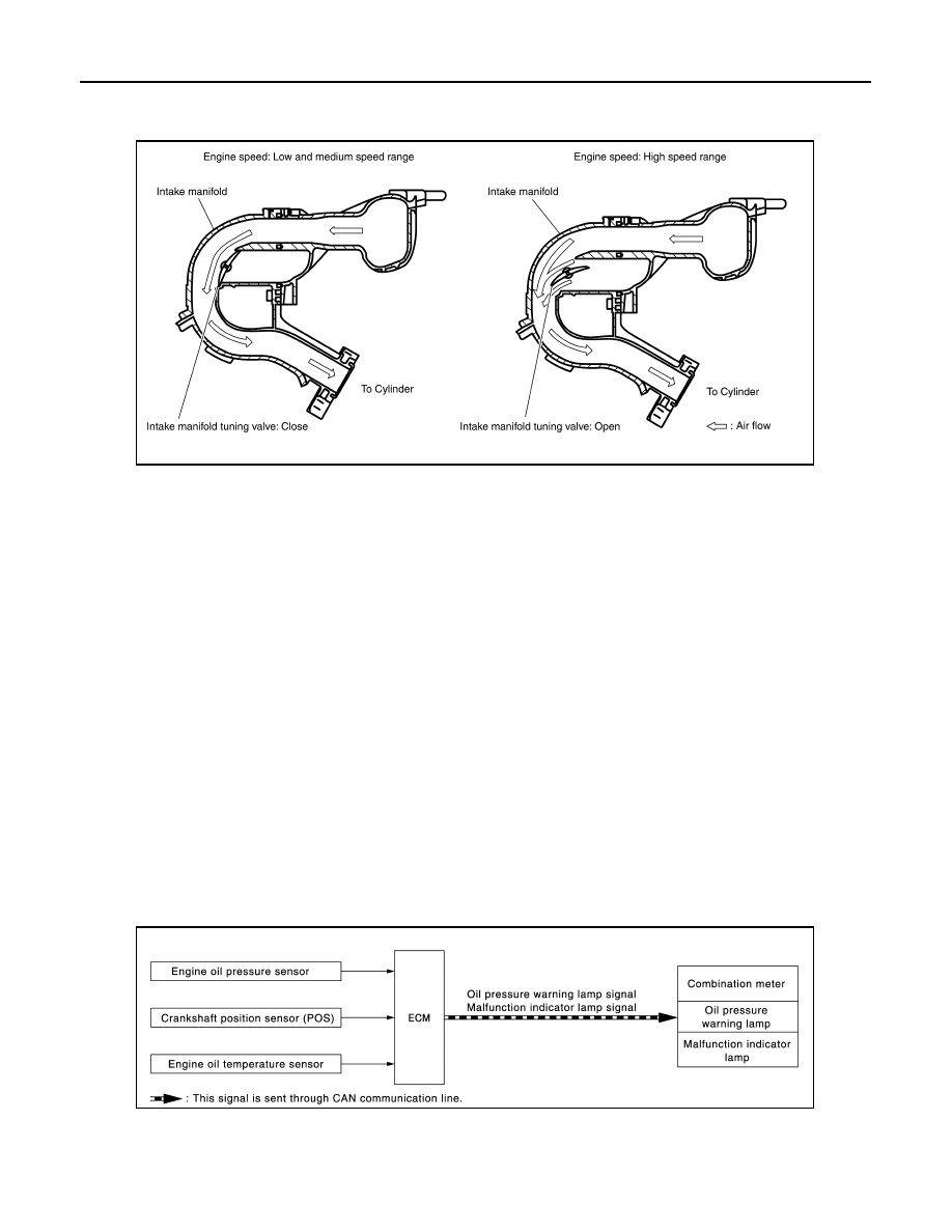
This system switches the length of intake air path according to the low-to-medium speed range or high speed

range. Torque is increased in the low-to-medium speed range and the engine output is improved in the high

speed range.

Engine speed: Low and medium speed range

Since the intake manifold tuning (IMT) valve is closed when the engine speed is less than 5,250 rpm, the

length of the effective intake air path is from the mouth of intake manifold collector to the intake valve. This

long path brings the inertia effect of intake air, contributing to the improvement in intake air efficiency and the

generation of high torque.

Engine speed: High speed range

When engine speed is 5,250 rpm or more, ECM turns ON the intake manifold tuning valve motor to open the

intake manifold tuning valve. The length of the effective intake air path at this time is from the intake manifold

tuning valve to the intake valve. This short path brings the inertia effect of intake air in the high speed range,

contributing to the torque improvement while the engine is running at high speeds. (The highest engine output

is improved.)

Intake Manifold Tuning Valve Operating Condition 

ECM opens the intake manifold tuning valve when all of the following conditions are satisfied.

• Engine speed: 5,250 rpm or more

• Engine coolant temperature: -30

°C (-22°F) or more

• Battery voltage: between 11 V and 16 V

ENGINE PROTECTION CONTROL AT LOW ENGINE OIL PRESSURE
ENGINE PROTECTION CONTROL AT LOW ENGINE OIL PRESSURE : System De-
scription

INFOID:0000000009758368

SYSTEM DIAGRAM

INPUT/OUTPUT SIGNAL CHART

JSBIA2818GB

JPBIA4922GB

SYSTEM

EC-45

< SYSTEM DESCRIPTION >

[MRA8DE]

C

D

E

F

G

H

I

J

K

L

M

A

EC

N

P

O

SYSTEM DESCRIPTION

• The engine protection control at low engine oil pressure warns the driver of a decrease in engine oil pres-

sure by the oil pressure warning lamp a before the engine becomes damaged.

• When detecting a decrease in engine oil pressure at an engine speed less than 1,000 rpm, ECM transmits

an oil pressure warning lamp signal to the combination meter.The combination meter turns ON the oil pres-

sure warning lamp, according to the signal.

*: When detecting a normal engine oil pressure, ECM turns OFF the oil pressure warning lamp.

FUEL FILLER CAP WARNING SYSTEM
FUEL FILLER CAP WARNING SYSTEM : System Description

INFOID:0000000009758369

SYSTEM DIAGRAM

SYSTEM DESCRIPTION

The fuel filler cap warning system alerts the driver to the prevention of the fuel filler being left uncapped and

malfunction occurrences after refueling, by turning ON the fuel filler cap warning display on the combination

meter.

ECM judges a refueled state, based on a fuel level signal transmitted from the combination meter.

When a very small leak is detected through the EVAP leak diagnosis performed after judging the refueled

state, ECM transmits a fuel filler cap warning display signal (request for display ON) to the combination meter

via CAN communication. 

When receiving the signal, the combination meter turns ON the fuel filler cap warning display.

CAUTION:

Check fuel filler cap installation condition when the fuel filler cap warning display turns ON.

Reset Operation

The fuel filler cap warning lamp tunes OFF, according to any condition listed below:

Sensor

Input signal to ECM

ECM function

Actuator

Engine oil pressure sensor

Engine oil pressure

Engine protection control
• Oil pressure warning lamp 

signal

• Fuel cut control

Combination meter
• Oil pressure warning lamp

Crankshaft position sensor 
(POS)

Engine speed

Engine oil temperature sensor

Engine oil temperature

Decrease in engine oil 

pressure

Engine speed

Combination meter

Fuel cut

Oil pressure warning lamp

Detection

Less than 1,000 rpm

ON*

NO

1,000 rpm or more

ON

YES

JSBIA0797GB

EC-46

< SYSTEM DESCRIPTION >

[MRA8DE]

SYSTEM

• Reset operation is performed by operating the meter control switch on the combination meter. Refer to 

MWI-

16, "Description"

.

- When the reset operation is performed, the combination meter transmits a fuel filler cap warning reset signal

to ECM via CAN communication. ECM transmits a fuel filler cap warning display signal (request for display

OFF) to the combination meter via CAN communication. When receiving the signal, the combination meter

turns OFF the fuel filler cap warning display.

• EVAP leak diagnosis result is normal.

• Fuel refilled.

• DTC erased by using CONSULT.

NOTE:

MIL turns ON if a malfunction is detected in leak diagnosis results again at the trip after the fuel filler cap warn-

ing display turns ON/OFF.

AIR CONDITIONING CUT CONTROL
AIR CONDITIONING CUT CONTROL : System Description

INFOID:0000000009758370

SYSTEM DIAGRAM

INPUT/OUTPUT SIGNAL CHART

JSBIA2814GB

SYSTEM

EC-47

< SYSTEM DESCRIPTION >

[MRA8DE]

C

D

E

F

G

H

I

J

K

L

M

A

EC

N

P

O

*: ECM determines the start signal status by the signals of engine speed and battery voltage.

SYSTEM DESCRIPTION

This system improves engine operation when the air conditioner is used.

Under the following conditions, the air conditioner is turned off.

• When the accelerator pedal is fully depressed.

• When cranking the engine.

• At high engine speeds.

• When the engine coolant temperature becomes excessively high.

• When operating power steering during low engine speed or low vehicle speed.

• When engine speed is excessively low.

• When refrigerant pressure is excessively low or high.

COOLING FAN CONTROL
COOLING FAN CONTROL : System Description

INFOID:0000000009758371

SYSTEM DIAGRAM

Sensor

Input Signal to ECM

ECM function

Actuator

Crankshaft position sensor (POS)

Engine speed

*

Piston position

Air conditioner 
cut control

IPDM E/R

Air conditioner relay

Compressor

Camshaft position sensor (PHASE)

Engine coolant temperature sensor

Engine coolant temperature

Accelerator pedal position sensor

Accelerator pedal position

Battery

Battery voltage

*

Refrigerant pressure sensor

Refrigerant pressure

EPS control unit

CAN commu-
nication

EPS operation signal

Combination meter

CAN commu-
nication

Vehicle speed signal

A/C auto amp.

CAN commu-
nication

• A/C ON signal
• Blower fan ON signal

JSBIA2816GB


Content   ..  335  336  337  338   ..