Nissan Sentra. Manual - part 296


  Index      Nissan     Nissan Sentra (2014 year) - Service and Repair Manual


Search            


Content   ..  294  295  296  297   ..


Nissan Sentra. Manual - part 296


DLK-300

< REMOVAL AND INSTALLATION >

[WITHOUT INTELLIGENT KEY SYSTEM]

HOOD

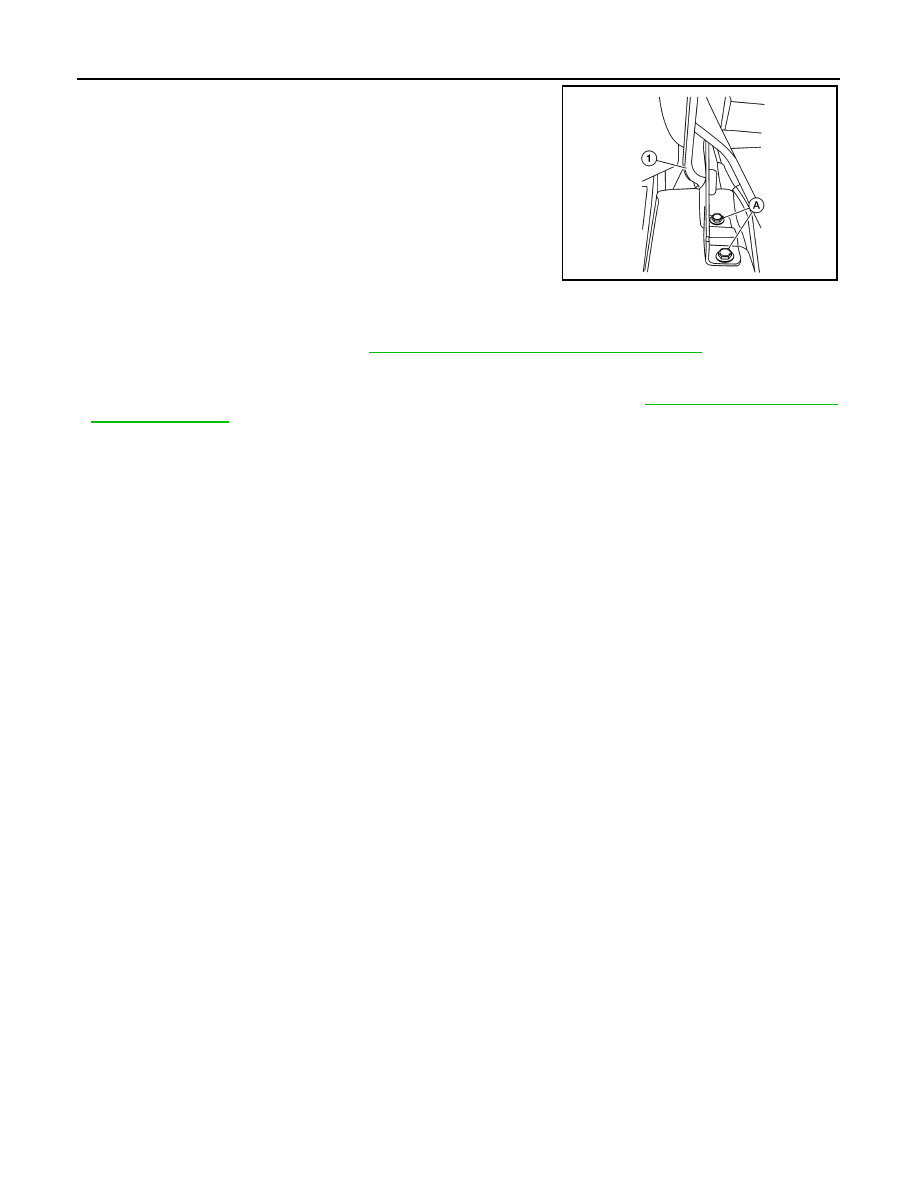
6. Remove hood hinge bolts (A) and hood hinge (1).

INSTALLATION

Installation is in the reverse order of removal.

Tighten bolts to specified torque. Refer to 

DLK-149, "HOOD ASSEMBLY : Exploded View"

.

CAUTION:

• Before installing the hood hinge, apply anticorrosive agent onto the surface of the vehicle.

• After installation, perform hood assembly adjustment procedure. Refer to 

DLK-297, "HOOD ASSEM-

BLY : Adjustment"

.

HOOD SUPPORT ROD
HOOD SUPPORT ROD : Removal and Installation

INFOID:0000000009756620

REMOVAL

1. Support hood assembly using a suitable tool.

WARNING:

Bodily injury may occur if hood assembly is not supported properly when removing hood support

rod.

2. Rotate and remove hood support rod from grommet.
3. Remove grommet from hood hinge using a suitable tool, if necessary.

INSTALLATION

Installation is in the reverse order of removal.

HOOD LOCK CONTROL

ALKIA2891ZZ

HOOD

DLK-301

< REMOVAL AND INSTALLATION >

[WITHOUT INTELLIGENT KEY SYSTEM]

C

D

E

F

G

H

I

J

L

M

A

B

DLK

N

O

P

HOOD LOCK CONTROL : Exploded View

INFOID:0000000009756621

HOOD LOCK CONTROL : Removal and Installation

INFOID:0000000009756622

REMOVAL

1. Remove the fender protector (LH). Refer to 

EXT-28, "FENDER PROTECTOR : Removal and Installation -

Front Fender Protector"

.

2. Remove the radiator core support upper cover clips (A) and

bolts (B) and remove.

1.

Hood lock assembly

2.

Hood lock release cable

3.

Hood lock/fuel filler door release handle assembly

A.

Hood lock release cable clip

Clip

AWKIA2088ZZ

AWKIA2156ZZ

DLK-302

< REMOVAL AND INSTALLATION >

[WITHOUT INTELLIGENT KEY SYSTEM]

HOOD

3. Remove the hood lock assembly bolts (A).

4. Disconnect the hood lock release cable from the hood lock assembly.
5. Remove the bolts (A), then separate the hood lock/fuel filler door

release handle assembly (1) from the hood lock release cable

(3) and fuel filler door release cable (2).

6. Remove the grommet from the dash assembly and pull the hood lock release cable into the passenger

compartment.

CAUTION:

While pulling, be careful not to damage (peel) the outside of the hood lock release cable.

INSTALLATION

1. Pull the hood lock release cable through the dash assembly into the engine compartment.

CAUTION:

Be careful not to bend the cable too much, keep the radius 100 mm (3.94 in) or more.

2. Attach the hood lock release cable (3) and the fuel filler door

release cable (2) to the hood lock/fuel filler door release handle

assembly (1).

3. Place hood lock/fuel filler door release handle assembly in posi-

tion and retain with bolts (A).

4. Check that the cable is not offset from the center of the grommet

and seat the grommet into the dash hole.

NOTE:

Make sure that the marked area (A) of the cable is located as

shown after mounting grommet to dash upper assembly.

Apply sealant around the grommet at * mark.

5. Position the hood lock release cable and clip it into place.

ALKIA2892ZZ

ALKIA2893ZZ

ALKIA2893ZZ

ALKIA2139ZZ

HOOD

DLK-303

< REMOVAL AND INSTALLATION >

[WITHOUT INTELLIGENT KEY SYSTEM]

C

D

E

F

G

H

I

J

L

M

A

B

DLK

N

O

P

6. Connect the hood lock release cable to the hood lock assembly.

7. Perform hood fitting adjustment. Refer to 

DLK-297, "HOOD ASSEMBLY : Adjustment"

8. Perform the hood lock control inspection. 

INSPECTION

NOTE:

If the hood lock release cable is bent or deformed, replace it.
1. Check that the secondary latch is properly engaged with the secondary striker and meets specification

provided (B) with hood's own weight.

2. While operating the hood lock release handle, carefully check that the front end of the hood assembly is

raised and meets the specification provided (A). Also check that the hood lock release handle returns to

the original position.

3. Check that the hood lock release handle operating force is 49 N (5.0 kg, 11 lb) or less.
4. Install so the static closing force of the hood assembly is 49 – 490 N (5.0 – 50 kg-f, 36 - 110.2 lb-f).
5. Check the hood lock assembly lubrication condition. If neces-

sary, apply a suitable multi-purpose grease as shown.

PIIB5802E

1.

Hood striker

2.

Primary latch

3.

Secondary striker

4.

Secondary latch

A.

21 

± 1mm (0.8 ±0.04 in)

B.

6.8 mm (0.27 in)

PIIB5794E

ALKIA0028GB


Content   ..  294  295  296  297   ..