Nissan Sentra. Manual - part 207


  Index      Nissan     Nissan Sentra (2014 year) - Service and Repair Manual


Search            


Content   ..  205  206  207  208   ..


Nissan Sentra. Manual - part 207


CLUTCH MASTER CYLINDER

CL-13

< REMOVAL AND INSTALLATION >

C

E

F

G

H

I

J

K

L

M

A

B

CL

N

O

P

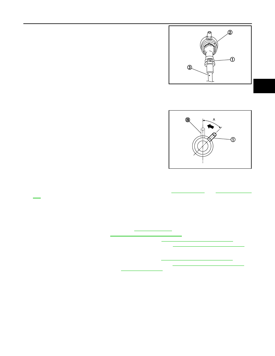
5. Pull up the lock pin (1) from connector of clutch master cylinder

(2) and separate clutch tube (3).

6. Rotate clutch master cylinder clockwise by 45 degrees, and then

remove clutch master cylinder from the vehicle.

INSTALLATION

CAUTION:

Keep painted surface on the body or other parts free of clutch fluid. If it spills, wipe up immediately

and wash the affected area with water.
1. With the nipple (1) rotated clockwise by 45 degrees, insert clutch

mastery cylinder into the mounting hole. Rotate the clutch mas-

ter cylinder counterclockwise by 45 degrees (A) as show to

secure it. At this time, nipple (1) is in the upward (B) position.

2. Install clutch master cylinder rod end to clutch pedal.

CAUTION:

Press clutch master cylinder rod end into clutch pedal until

it stops.

3. Install reservoir hose to reservoir tank and clutch master cylin-

der.

CAUTION:

Rotate reservoir hose with painted mark facing upward.

4. Press down the lock pin into connector of clutch master cylinder until it stops.
5. Install clutch tube into connector of clutch master cylinder until it stops.
6. Fill with clutch fluid and perform air bleeding procedure. Refer to 

CL-8, "Refilling"

 and 

CL-9, "Air Bleed-

ing"

.

7. Installation of the remaining components is in the reverse order of removal.

Inspection and Adjustment

INFOID:0000000009757030

INSPECTION AFTER INSTALLATION

• Check for fluid leakage and the fluid level. Refer to 

CL-7, "Inspection"

.

• Check the clutch pedal height. Refer to 

CL-5, "Inspection and Adjustment"

.

• Check the clutch interlock switch position (if equipped). Refer to 

CL-5, "Inspection and Adjustment"

.

• Check the clutch pedal position switch position (if equipped). Refer to 

CL-5, "Inspection and Adjustment"

.

ADJUSTMENT AFTER INSTALLATION

• Adjust the clutch interlock switch position (if equipped). Refer to 

CL-5, "Inspection and Adjustment"

.

• Adjust the clutch pedal position switch position (if equipped). Refer to 

CL-5, "Inspection and Adjustment"

.

• Perform the air bleeding procedure. Refer to 

CL-9, "Air Bleeding"

.

JPDIB0167ZZ

JPDIB0114ZZ

CL-14

< REMOVAL AND INSTALLATION >

CLUTCH PIPING

CLUTCH PIPING

Exploded View

INFOID:0000000009757031

Hydraulic Layout

INFOID:0000000009757032

Removal and Installation

INFOID:0000000009757033

CAUTION:

Keep painted surface on the body or other parts free of clutch fluid. If it spills, wipe up immediately

and wash the affected area with water.

NOTE:

When removing components such as hoses, tubes/lines, etc., cap or plug openings to prevent fluid from spill-

ing.

1.

CSC (Concentric Slave Cylinder)

2.

Clip

3

Clutch tube

4.

Clutch damper

5.

Bracket

6.

Clutch master cylinder

JSDIA3642ZZ

1.

Clutch tube

2.

Lock pin

3.

CSC (Concentric Slave Cylinder)

4.

Clutch damper

5.

Clutch master cylinder

6.

Clutch pedal

PCIB1499E

CLUTCH PIPING

CL-15

< REMOVAL AND INSTALLATION >

C

E

F

G

H

I

J

K

L

M

A

B

CL

N

O

P

REMOVAL 

1. Drain clutch fluid. Refer to 

CL-7, "Draining"

.

2. Press the lock pin into the bleeding connector of the CSC, and then remove clutch tube from CSC.
3. Pull outward on the lock pins from the connectors of the clutch damper until the pins stop, and then

remove clutch tubes from clutch damper.

4. Pull outward on the lock pin from the connector of the clutch master cylinder until the pin stops, and then

remove clutch tube from clutch master cylinder.

INSTALLATION

Installation is in the reverse order of removal.

CAUTION:

Do not damage clutch tube.

• Insert each clutch tube into the CSC bleeding connector, the clutch damper connector, and the clutch master

cylinder connector until it contacts the end of each connector.

• Install each lock pin into the clutch damper connector and the clutch master cylinder connector until it con-

tacts the end of each connector.

Inspection and Adjustment

INFOID:0000000009757034

INSPECTION AFTER REMOVAL

• Check the clutch tube for cracks and damage. If the clutch tube has cracks or damage, replace it with a new

one.

• Check the O-ring of the clutch tube for cracks and damage. If the O-ring of the clutch tube has cracks or

damage, replace clutch tube with a new one.

CAUTION:

Do not reuse O-rings.

• Check the clutch damper for cracks and damage. If the clutch damper has cracks or damage, replace it with

a new one.

INSPECTION AFTER INSTALLATION

• Check the fluid leakage and the fluid level. Refer to 

CL-7, "Inspection"

.

• Check the clutch pedal height. Refer to 

CL-5, "Inspection and Adjustment"

.

ADJUSTMENT AFTER INSTALLATION

Perform the air bleeding procedure. Refer to 

CL-9, "Air Bleeding"

.

CL-16

< REMOVAL AND INSTALLATION >

CSC (CONCENTRIC SLAVE CYLINDER)

CSC (CONCENTRIC SLAVE CYLINDER)

Exploded View

INFOID:0000000009757035

Removal and Installation

INFOID:0000000009757036

CAUTION:

• Do not reuse CSC (Concentric Slave Cylinder). The CSC slides back to the original position every

time the transaxle assembly is removed. This action may allow dust or contaminants to gather on

the sliding parts and damage a seal of CSC causing clutch fluid leakage.

• Do not disassemble CSC.

• Keep painted surface on the body or other parts free of clutch fluid. If clutch fluid spills, wipe up

immediately and wash the affected area with water.

REMOVAL

1. Remove engine and transaxle assembly. Refer to 

TM-28, "Removal and Installation"

.

2. Remove CSC bolts, then remove the CSC from transaxle assembly.

INSTALLATION

1. Install CSC to transaxle assembly, then tighten CSC bolts to the specified torque.

CAUTION:

• Do not reuse CSC.

• Do not install then operate CSC immediately, the piston and stopper of CSC components may

fall off.

2. Install engine and transaxle assembly in the reverse order of removal. Refer to 

TM-28, "Removal and

Installation"

.

Inspection and Adjustment

INFOID:0000000009757037

INSPECTION AFTER INSTALLATION

Check for fluid leakage and the fluid level. Refer 

CL-7, "Inspection"

.

ADJUSTMENT AFTER INSTALLATION

Perform the air bleeding. Refer to 

CL-9, "Air Bleeding"

.

1.

Transaxle assembly

2.

CSC (Concentric Slave Cylinder)

JPDIB0040GB


Content   ..  205  206  207  208   ..