Nissan Sentra. Manual - part 206


  Index      Nissan     Nissan Sentra (2014 year) - Service and Repair Manual


Search            


Content   ..  204  205  206  207   ..


Nissan Sentra. Manual - part 206


CLUTCH FLUID

CL-9

< PERIODIC MAINTENANCE >

C

E

F

G

H

I

J

K

L

M

A

B

CL

N

O

P

7. Return clutch tube and lock pin in their original positions while clutch pedal is depressed.
8. Perform the air bleeding. Refer to 

CL-9, "Air Bleeding"

.

Air Bleeding

INFOID:0000000009757024

CAUTION:

• Monitor clutch fluid level in reservoir tank so as not to empty the tank.

• Do not spill clutch fluid onto painted surfaces. If fluid spills, wipe up immediately and wash the

affected area with water.

1. Fill reservoir tank with new clutch fluid.

CAUTION:

Do not reuse drained clutch fluid.

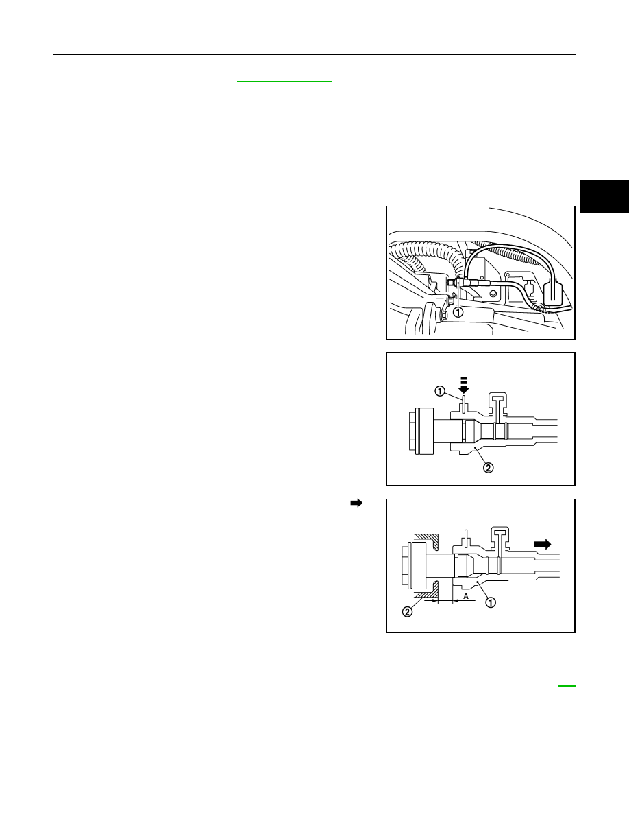
2. Connect a transparent vinyl hose to air bleeder of bleeding con-

nector (1).

3. Depress and release the clutch pedal slowly and fully 15 times

at an interval of 2 to 3 seconds and release the clutch pedal.

4. Press the lock pin (1) into the bleeding connector (2), and main-

tain the position.

5. Slide bleeding connector (1) in the direction of the arrow ( ) as

shown and immediately depress the clutch pedal and hold it, to

bleed the air from the system.

CAUTION:

Clutch tube is under hydraulic pressure; do not allow the

clutch tube to disconnect from the clutch housing.

6. Return clutch tube and lock pin in their original positions.
7. Release clutch pedal and wait for 5 seconds.
8. Repeat steps 3 to 7 until no bubbles are observed in the clutch fluid.
9. Check that the fluid level in the reservoir tank is within the specified range after air bleeding. Refer to 

CL-

7, "Inspection"

.

JPDIB0166ZZ

JPDIB0041ZZ

(2)

: Clutch housing

Dimension (A)

: 10 mm (0.39 in)

JPDIB0042ZZ

CL-10

< REMOVAL AND INSTALLATION >

CLUTCH PEDAL

REMOVAL AND INSTALLATION

CLUTCH PEDAL

Exploded View

INFOID:0000000009757025

Removal and Installation

INFOID:0000000009757026

REMOVAL

1. Remove instrument lower panel LH. Refer to 

IP-21, "Removal and Installation"

.

2. Disconnect the harness connector from the clutch pedal position switch (if equipped).
3. Disconnect the harness connector from the clutch interlock switch (if equipped).
4. Disconnect clip of harness from clutch pedal.
5. Remove clutch master cylinder rod end from clutch pedal.
6. Remove clutch pedal position switch and clip from clutch pedal

(if equipped).

7. Remove clutch interlock switch and clip from clutch pedal (if

equipped).

8. Remove clutch pedal from the vehicle.
9. Remove pedal pad from clutch pedal.
10. Remove stopper rubber and pedal stopper rubber from clutch

pedal, using a suitable remover.

INSTALLATION

Installation is in the reverse order of removal.

1.

Clutch pedal

2.

Stopper rubber

3.

Clip

4.

Clutch interlock switch (if equipped) 5.

Clutch pedal position switch (if equipped) 6.

Pedal pad

7.

Pedal stopper rubber

JSDIA3615GB

PCIB1491E

CLUTCH PEDAL

CL-11

< REMOVAL AND INSTALLATION >

C

E

F

G

H

I

J

K

L

M

A

B

CL

N

O

P

CAUTION:

After applying recommended grease, press clutch master cylinder rod end into clutch pedal until it

stops.

Inspection and Adjustment

INFOID:0000000009757027

INSPECTION AFTER REMOVAL

• Check clutch pedal for bend, damage, or a cracked weld. If bend, damage, or a cracked weld is found,

replace clutch pedal.

• Check pedal stopper rubber (if equipped). If damage or deformation is found, replace pedal stopper rubber.

(if equipped)

• Check stopper rubber. If damage or deformation is found, replace stopper rubber.

• Check pedal pad. If wear or damage is found, replace pedal pad.

INSPECTION AFTER INSTALLATION

• Check the height of clutch pedal. Refer to 

CL-5, "Inspection and Adjustment"

.

• Check the clutch interlock switch position (if equipped). Refer to 

CL-5, "Inspection and Adjustment"

.

• Check the clutch pedal position switch position (if equipped). Refer to 

CL-5, "Inspection and Adjustment"

.

ADJUSTMENT AFTER INSTALLATION

• Adjust the clutch interlock switch position (if equipped). Refer to 

CL-5, "Inspection and Adjustment"

.

• Adjust the clutch pedal position switch position (if equipped). Refer to 

CL-5, "Inspection and Adjustment"

.

CL-12

< REMOVAL AND INSTALLATION >

CLUTCH MASTER CYLINDER

CLUTCH MASTER CYLINDER

Exploded View

INFOID:0000000009757028

Removal and Installation

INFOID:0000000009757029

REMOVAL

CAUTION:

• Keep painted surface on the body or other parts free of clutch fluid. If it spills, wipe up immediately

and wash the affected area with water.

• Do not disassemble clutch master cylinder.

NOTE:

When removing components such as hoses, tubes/lines, etc., cap or plug openings to prevent fluid from spill-

ing.
1. Drain clutch fluid. Refer to 

CL-7, "Draining"

.

2. Remove air cleaner body assembly. Refer to 

EM-25, "Removal and Installation"

.

3. Remove reservoir hose from reservoir tank and clutch master cylinder.
4. Remove clutch master cylinder rod end (

) from clutch pedal.

1.

Reservoir hose

2.

Reservoir tank

3.

Clutch master cylinder

ALDIA0405ZZ

PCIB1491E


Content   ..  204  205  206  207   ..