Nissan Sentra. Manual - part 173
C1142 PRESS SENSOR
BRC-79
< DTC/CIRCUIT DIAGNOSIS >
[VDC/TCS/ABS]
C
D
E
G
H
I
J
K
L
M
A
B
BRC
N
O
P
C1142 PRESS SENSOR
DTC Logic
INFOID:0000000009757858
DTC DETECTION LOGIC
DTC CONFIRMATION PROCEDURE
1.
CHECK SELF DIAGNOSTIC RESULT
With CONSULT.
1. Turn ignition switch ON.
2. Perform self diagnostic result.
Is DTC C1142 detected?
YES
>> Proceed to diagnosis procedure. Refer to
.
NO
>> Inspection End.
Diagnosis Procedure
INFOID:0000000009757859
1.
CHECK STOP LAMP SWITCH SYSTEM
Check stop lamp switch system. Refer to
Is the inspection result normal?
YES
>> GO TO 2.
NO
>> Repair or replace malfunctioning components.
2.
CHECK BRAKE FLUID LEAKAGE
Check brake fluid leakage. Refer to
Is the inspection result normal?
YES
>> GO TO 3.
NO
>> Repair or replace malfunctioning components.
3.
CHECK BRAKE PEDAL
Check brake pedal. Refer to
Is the inspection result normal?
YES
>> GO TO 4.
NO
>> Repair or replace malfunctioning components.
4.
CHECK SELF DIAGNOSTIC RESULT
With CONSULT.
1. Turn ignition switch ON.
2. Perform self diagnostic result.
3. Erase DTCs.
4. Start engine and drive vehicle for a short period of time.
5. Turn ignition switch ON.
6. Perform self diagnostic result.
Is DTC C1142 detected?
YES
>> Replace ABS actuator and electric unit (control unit). Refer to
BRC-110, "Removal and Installa-
.
NO
>> Inspection End.
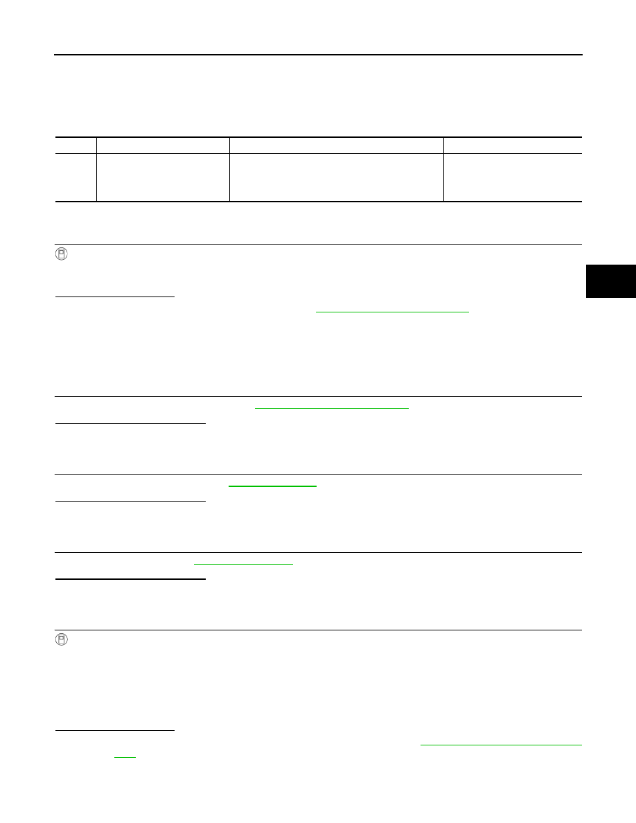
DTC
Display Item
Malfunction detected condition
Possible causes
C1142
PRESS SEN CIRCUIT
When a malfunction is detected in master cylinder
pressure sensor.
• Stop lamp switch system
• ABS actuator and electric unit
(control unit)
• Brake system