Nissan Sentra. Manual - part 171


  Index      Nissan     Nissan Sentra (2014 year) - Service and Repair Manual


Search            


Content   ..  169  170  171  172   ..


Nissan Sentra. Manual - part 171


C1116 STOP LAMP SWITCH

BRC-71

< DTC/CIRCUIT DIAGNOSIS >

[VDC/TCS/ABS]

C

D

E

G

H

I

J

K

L

M

A

B

BRC

N

O

P

Is the inspection result normal?

YES

>> GO TO 4.

NO

>> Repair or replace as necessary.

4.

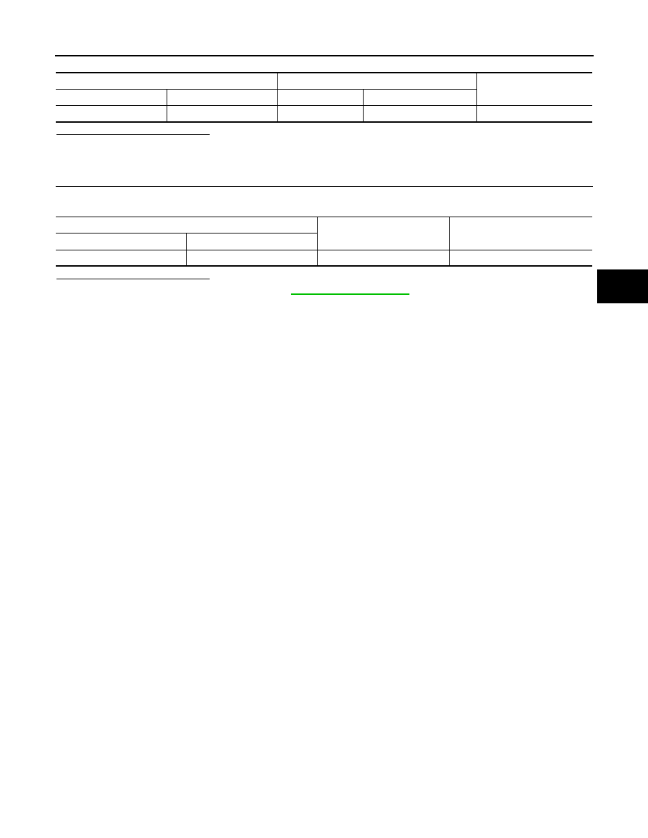
CHECK STOP LAMP SWITCH CIRCUIT FOR SHORT

Check continuity between ABS actuator and electric unit (control unit) connector E33 terminal 30 and ground.

Is the inspection result normal?

YES

>> Replace stop lamp switch. Refer to 

BR-22, "Exploded View"

NO

>> Repair harness or connectors.

ABS actuator and electric unit (control unit)

Stop lamp switch

Continuity

Connector

Terminal

Connector

Terminal

E33

30

E60

2

Yes

ABS actuator and electric unit (control unit)

Ground

Continuity

Connector

Terminal

E33

30

No

BRC-72

< DTC/CIRCUIT DIAGNOSIS >

[VDC/TCS/ABS]

C1120, C1122, C1124, C1126 ABS IN VALVE SYSTEM

C1120, C1122, C1124, C1126 ABS IN VALVE SYSTEM

DTC Logic

INFOID:0000000009757850

DTC DETECTION LOGIC

DTC CONFIRMATION PROCEDURE

1.

CHECK SELF DIAGNOSTIC RESULT

With CONSULT.

1. Turn ignition switch ON.

2. Perform self diagnostic result.
Is DTC C1120, C1122, C1124 or C1126 detected?

YES

>> Proceed to diagnosis procedure. Refer to 

BRC-72, "Diagnosis Procedure"

.

NO

>> Inspection End.

Diagnosis Procedure

INFOID:0000000009757851

Regarding Wiring Diagram information, refer to 

BRC-44, "Wiring Diagram"

.

1.

CONNECTOR INSPECTION

1. Turn ignition switch OFF.

2. Disconnect ABS actuator and electric unit (control unit) connector.

3. Check connector and terminals for deformation, disconnection, looseness or damage.
Is the inspection result normal?

YES

>> GO TO 2.

NO

>> Repair or replace as necessary.

2.

CHECK ABS ACTUATOR AND ELECTRIC UNIT (CONTROL UNIT) BATTERY POWER SUPPLY

Check voltage between ABS actuator and electric unit (control unit) connector E33 terminal 25 and ground.

Is the inspection result normal?

YES

>> GO TO 3.

NO

>> Repair or replace malfunctioning components.

3.

CHECK ABS ACTUATOR AND ELECTRIC UNIT (CONTROL UNIT) GROUND CIRCUIT

Check continuity between ABS actuator and electric unit (control unit) connector E33 terminals 13, 38 and

ground.

DTC

Display Item

Malfunction detected condition

Possible causes

C1120

FR LH IN ABS SOL

When a malfunction is detected in front LH ABS IN 
valve.

• Harness or connector
• ABS actuator and electric unit 

(control unit)

• Fusible link
• Battery power supply system

C1122

FR RH IN ABS SOL

When a malfunction is detected in front RH ABS IN 
valve.

C1124

RR LH IN ABS SOL

When a malfunction is detected in rear LH ABS IN 
valve.

C1126

RR RH IN ABS SOL

When a malfunction is detected in rear RH ABS IN 
valve.

ABS actuator and electric unit (control unit)

Voltage

(Approx.)

Connector

Terminal

E33

25

Ground

Battery voltage

C1120, C1122, C1124, C1126 ABS IN VALVE SYSTEM

BRC-73

< DTC/CIRCUIT DIAGNOSIS >

[VDC/TCS/ABS]

C

D

E

G

H

I

J

K

L

M

A

B

BRC

N

O

P

Is the inspection result normal?

YES

>> Replace ABS actuator and electric unit (control unit). Refer to 

BRC-110, "Removal and Installa-

tion"

.

NO

>> Repair or replace malfunctioning components.

ABS actuator and electric unit (control unit)

Continuity

Connector

Terminal

E33

13

Ground

Yes

38

BRC-74

< DTC/CIRCUIT DIAGNOSIS >

[VDC/TCS/ABS]

C1121, C1123, C1125, C1127 ABS OUT VALVE SYSTEM

C1121, C1123, C1125, C1127 ABS OUT VALVE SYSTEM

DTC Logic

INFOID:0000000009757852

DTC DETECTION LOGIC

DTC CONFIRMATION PROCEDURE

1.

CHECK SELF DIAGNOSTIC RESULT

With CONSULT.

1. Turn ignition switch ON.

2. Perform self diagnostic result.
Is DTC C1121, C1123, C1125 or C1127 detected?

YES

>> Proceed to diagnosis procedure. Refer to 

BRC-74, "Diagnosis Procedure"

.

NO

>> Inspection End.

Diagnosis Procedure

INFOID:0000000009757853

Regarding Wiring Diagram information, refer to 

BRC-44, "Wiring Diagram"

.

1.

CONNECTOR INSPECTION

1. Turn ignition switch OFF.

2. Disconnect ABS actuator and electric unit (control unit) connector.

3. Check connector and terminals for deformation, disconnection, looseness or damage.
Is the inspection result normal?

YES

>> GO TO 2.

NO

>> Repair or replace as necessary.

2.

CHECK ABS ACTUATOR AND ELECTRIC UNIT (CONTROL UNIT) BATTERY POWER SUPPLY

Check voltage between ABS actuator and electric unit (control unit) connector E33 terminal 25 and ground.

Is the inspection result normal?

YES

>> GO TO 3.

NO

>> Repair or replace malfunctioning components.

3.

CHECK ABS ACTUATOR AND ELECTRIC UNIT (CONTROL UNIT) GROUND CIRCUIT

Check continuity between ABS actuator and electric unit (control unit) connector E33 terminals 13, 38 and

ground.

DTC

Display Item

Malfunction detected condition

Possible causes

C1121

FR LH OUT ABS SOL

When a malfunction is detected in front LH ABS OUT 
valve.

• Harness or connector
• ABS actuator and electric unit 

(control unit)

• Fusible link
• Battery power supply system

C1123

FR RH OUT ABS SOL

When a malfunction is detected in front RH ABS OUT 
valve.

C1125

RR LH OUT ABS SOL

When a malfunction is detected in rear LH ABS OUT 
valve.

C1127

RR RH OUT ABS SOL

When a malfunction is detected in rear RH ABS OUT 
valve.

ABS actuator and electric unit (control unit)

Voltage

(Approx.)

Connector

Terminal

E33

25

Ground

Battery voltage


Content   ..  169  170  171  172   ..