Nissan Sentra. Manual - part 170
C1113, C1145, C1146 YAW RATE/SIDE/DECEL G SENSOR
BRC-67
< DTC/CIRCUIT DIAGNOSIS >
[VDC/TCS/ABS]
C
D
E
G
H
I
J
K
L
M
A
B
BRC
N
O
P
C1113, C1145, C1146 YAW RATE/SIDE/DECEL G SENSOR
DTC Logic
INFOID:0000000009757844
DTC DETECTION LOGIC
DTC CONFIRMATION PROCEDURE
1.
CHECK SELF DIAGNOSTIC RESULT
With CONSULT.
1. Turn ignition switch OFF to ON.
2. Perform self diagnostic result.
Is DTC C1113, C1145 or C1146 detected?
YES
>> Proceed to diagnosis procedure. Refer to
.
NO
>> Inspection End.
Diagnosis Procedure
INFOID:0000000009757845
1.
REPLACE ABS ACTUATOR AND ELECTRIC UNIT (CONTROL UNIT)
Replace ABS actuator and electric unit (control unit).
>> Replace ABS actuator and electric unit (control unit). Refer to
BRC-110, "Removal and Installa-
.
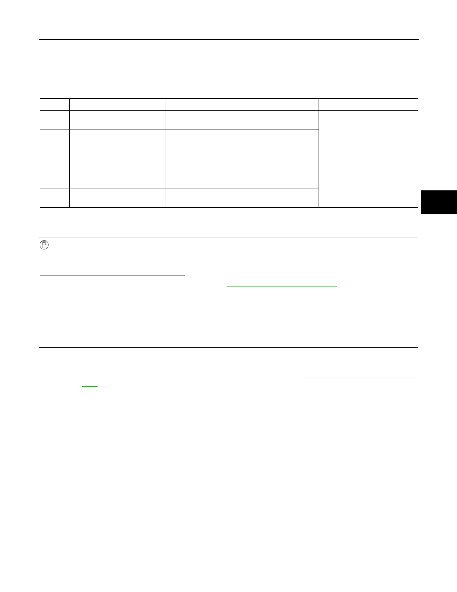
DTC
Display Item
Malfunction detected condition
Possible causes
C1113
G SENSOR
When a malfunction is detected in longitunal G sensor
signal.
• ABS actuator and electric unit
(control unit)
C1145
YAW RATE SENSOR
• When a malfunction is detected in yaw rate signal.
• When yaw rate signal is not continuously received
for 2 seconds or more.
• When side G signal is not continuously received for
2 seconds or more.
• When decel G signal is not continuously received
for 2 seconds or more.
C1146
SIDE G-SEN CIRCUIT
When a malfunction is detected in side/decel G sig-
nal.