Nissan Sentra. Manual - part 146


  Index      Nissan     Nissan Sentra (2014 year) - Service and Repair Manual


Search            


Content   ..  144  145  146  147   ..


Nissan Sentra. Manual - part 146


BR-26

< REMOVAL AND INSTALLATION >

BRAKE PIPING

FRONT : Hydraulic Piping

INFOID:0000000009756004
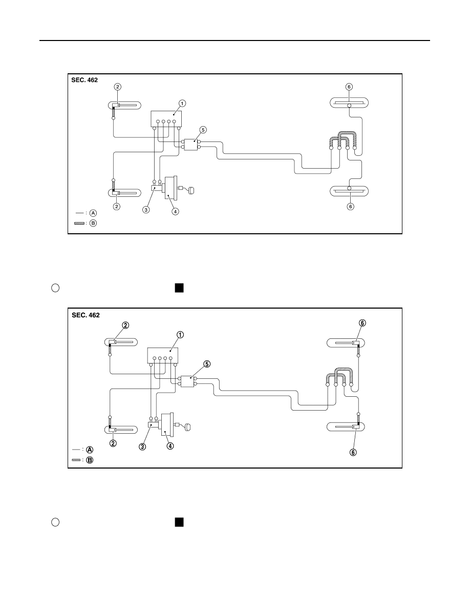
Drum Brake

Disc Brake

CAUTION:

• All hoses and piping (tubes) must be free from excessive bending, twisting and pulling.

• Make sure there is no interference with other parts when turning steering wheel both clockwise and

counterclockwise.

• The brake piping is an important safety part. If a brake fluid leak is detected, always disassemble the

parts. Replace applicable part with a new one, if necessary.

AWFIA0969ZZ

1.

ABS actuator and electric unit (con-
trol unit)

2.

Front disc brake

3.

Master cylinder assembly

4.

Brake booster

5.

Connector

6.

Rear drum brake

A.

Brake tube

B.

Brake hose

Flare nut

Union bolt

JSFIA1005ZZ

1.

ABS actuator and electric unit (con-
trol unit)

2.

Front disc brake

3.

Master cylinder assembly

4.

Brake booster

5.

Connector

6.

Rear disc brake

A.

Brake tube

B.

Brake hose

Flare nut

Union bolt

BRAKE PIPING

BR-27

< REMOVAL AND INSTALLATION >

C

D

E

G

H

I

J

K

L

M

A

B

BR

N

O

P

• Do not spill or splash brake fluid on painted surfaces. Brake fluid may damage paint. If brake fluid is

splashed on painted areas, wash it away with water immediately.

• Do not bend or twist brake hose sharply, or strongly pull it.

• When removing components, cover connections so that no dirt, dust, or other foreign matter gets in.

• Do not reuse drained brake fluid.

• After installation of the ABS actuator and electric unit (control unit), refill brake system with new

brake fluid. Then bleed the air from the system. Refer to 

BR-17, "Bleeding Brake System"

.

FRONT : Removal and Installation

INFOID:0000000009756005

NOTE:

When removing components such as hoses, tubes/lines, etc., cap or plug openings to prevent fluid from spill-

ing.

REMOVAL

1. Remove wheels and tires using power tool. Refer to 

WT-47, "Removal and Installation"

.

2. Drain brake fluid. Refer to 

BR-17, "Drain and Refill"

.

3. Loosen the flare nut with suitable tool and separate the brake pipe from the hose.

CAUTION:

• Do not scratch the flare nut and the brake pipe.

• All brake hoses and pipes must be free from excessive bending, twisting and pulling.

4. Remove the union bolt and the brake hose from the brake caliper assembly. Remove and discard the cop-

per sealing washers.

CAUTION:

Do not reuse copper sealing washers.

5. Remove the lock plate and remove the brake hose.

INSTALLATION

CAUTION:

Do not allow foreign matter (e.g. dust) and oils other than brake fluid to enter the reservoir tank.
1. Assemble the union bolt (A) and the copper sealing washers (1)

to the brake hose and install it as an assembly to the caliper.

Align the brake hose L-pin by aligning it with the brake caliper

assembly hole, and tighten the union bolt (1) to the specified

torque.

CAUTION:

Do not reuse copper sealing washers.

2. Install the brake pipe to the brake hose, temporarily tighten the

flare nut by hand until it does not rotate further, and secure the

brake hose to the bracket with the lock plate.

CAUTION:

Check that the brake hoses and pipes are not bent or

twisted.

3. Tighten the flare nut to the specified torque with a flare nut torque wrench.

CAUTION:

Do not scratch the flare nut and the brake tube.

4. Refill with new brake fluid and perform the air bleeding. Refer to 

BR-17, "Bleeding Brake System"

.

CAUTION:

Do not reuse drained brake fluid.

5. Install the wheels and tires. Refer to 

WT-47, "Removal and Installation"

.

REAR

AWFIA0795ZZ

BR-28

< REMOVAL AND INSTALLATION >

BRAKE PIPING

REAR : Exploded View

INFOID:0000000009756006

Drum Brake

Disc Brake

AWFIA0975ZZ

1.

Brake tube

2.

Brake hose

3.

Lock plate

A.

To drum brake

B.

To brake pipe connector

Front

AWFIA0974ZZ

BRAKE PIPING

BR-29

< REMOVAL AND INSTALLATION >

C

D

E

G

H

I

J

K

L

M

A

B

BR

N

O

P

REAR : Hydraulic Piping

INFOID:0000000009756007

Drum Brake

Disc Brake

1.

Brake tube

2.

Brake hose

3.

Lock plate

4.

Brake hose bracket

5.

Union bolt

6.

Rear brake hose 

7.

Copper sealing washer

A.

To disc brake

B.

To brake pipe connector

Front

AWFIA0969ZZ

1.

ABS actuator and electric unit (con-
trol unit)

2.

Front disc brake

3.

Master cylinder assembly

4.

Brake booster

5.

Connector

6.

Rear drum brake

A.

Brake tube

B.

Brake hose

Flare nut

Union bolt

JSFIA1005ZZ

1.

ABS actuator and electric unit (con-
trol unit)

2.

Front disc brake

3.

Master cylinder assembly

4.

Brake booster

5.

Connector

6.

Rear disc brake

A.

Brake tube

B.

Brake hose

Flare nut

Union bolt


Content   ..  144  145  146  147   ..